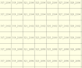
An example of a tile layout is shown below. In this example, the tiles are named according to the lower left coordinates i.e. X_Y, where X = x coordinate divided by 1000 and Y = y coordinate divided by 1000; and a tile has a width of 2000 meters and a height of 2000 meters.

Global Mapper can be used to create the grid tile layout from a region of interest polygon.
- Start Global Mapper. Load and display the region of interest polygon.
- Press ALT+C to display the Overlay Control Center.

- In the Overlay Control Center, select the region of interest layer. Click Metadata.
The Metadata dialog box appears.
- Take note of the UPPER LEFT X, UPPER LEFT Y, LOWER RIGHT X, and LOWER RIGHT Y attributes.
- Since the UPPER LEFT X value is 305458, an appropriate grid origin x value would be 305000, i.e. a round down.
- Since the UPPER LEFT Y value is 2119255, an appropriate grid origin y value would be 2120000, i.e. a round up.
- Since the difference between the LOWER RIGHT X and UPPER LEFT X is 55326 (360784 - 305458), then an appropriate number of grid columns would be 28, i.e. 55326/2000 where 2000 is the grid width.
- Since the difference between the UPPER LEFT Y and LOWER RIGHT Y is 41187 (2119255 - 2078068), then an appropriate number of grid rows would be 21, i.e. 41187/2000 where 2000 is the grid height.
- Close the Metadata dialog box.
- Select ALT+D. Click the Create Regular Grid of Features
 icon.
icon.
The status bar shows the message "Left Click to Select Grid Anchor Point, ...". - Click a point anywhere inside the map window.
The Grid Setup dialog box appears.
- In the Number of Grid Rows field, type in 21.
- In the Number of Grid Columns field, type in 28.
- In the Grid Cell Width field, type in 2000 meters.
- In the Grid Cell Height field, type in 2000 meters.
- Click Anchor Point.
The Select Location dialog box appears.
- In the X Coordinate field, type in 305000.
- In the Y Coordinate field, type in 2120000.
- Click OK.
- Toggle on Separate Row/Column Letters or Numbers. Toggle on Numbers.
- In the Rows Start field, type in 2120. In the Rows Step field, type in -2.
- In the Columns Start field, type in 305. In the Columns Step field, type in 2.
- Toggle on Reverse Naming, Prepend 0, and Separate Rows and Columns with Underscore.

- Click OK.
The grid tile layout is created.

No comments:
Post a Comment