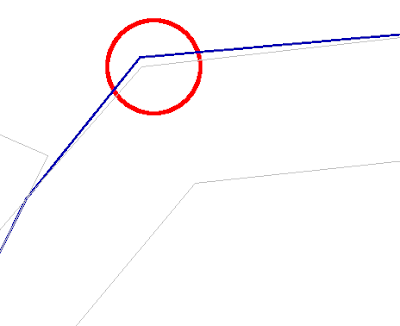
As there were hundreds of thousands of geometries to be processed, doing it interactively was out of the question and the job had to be done in batch mode. I did some research and learnt about the Anchored Snapper factory in SAFE FME Professional. Here I describe how to perform snapping of geometries using the Anchored Snapper.
- Open up the FME Workbench and define the source dataset for the candidate geometries for snapping (e.g. land use) and the anchor geometries (e.g. land parcels).
- Add in the Anchored Snapper factory and define the following parameters.

Note: Enter a suitable snapping tolerance for your dataset. - Define the destination datasets.
I defined destination datasets for the snapped geometries, the untouched geometries, and the combined snapped and untouched geometries. - Connect up all the datasets and the factory as shown in the figure below.

- Run the conversion.
The results of the snapping are shown below. The red linework is the new snapped geometry while the light blue linework is the unsnapped geometry.

No comments:
Post a Comment