Showing posts with label Global Mapper. Show all posts

Monday, July 17, 2017

Use PDAL to generate a DEM from a LiDAR LAS file

PDAL can be used to generate a GeoTIFF digital elevation model (DEM) from a LiDAR point cloud LAS file via the GDAL writer driver. The resultant elevation GeoTIFF file may not be displayed as what is expected in some software such as Global Mapper because the PDAL generated file can have one or more bands of data including an alpha channel, depending on the PDAL options used; refer to https://www.pdal.io/stages/writers.gdal.html for the types of output bands that can be written to the DEM GeoTIFF file. For normal display, it might be necessary to separate the bands into individual files - in this post, the OTB (Orfeo Tool Box) otbcli_splitImage executable is used.

The following steps show how to generate a GeoTIFF DEM and split the resultant file into separate bands.

Generate the DEM

  1. Open up a text editor. Type in the following JSON text. Save the text into a file e.g. pdal_dtm.json
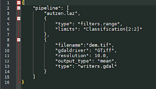


    Note: the JSON pipeline text will do the following:
    (a) Load in a LAS file e.g. autzen.laz
    (b) Filter away non-ground classified point
    (c) Write only the mean Z values to a GeoTIFF file dem.tif with a resolution of 10 meters

  2. Open up the OSGeo4W Command Prompt.

    The Command Prompt appears.
  3. Type in the PDAL command to process the pipeline. Run the command.

    C:\> pdal pipeline pdal_dtm.json

    The GeoTIFF file dem.tif is generated.
Splitting the bands

Displaying the resultant dem.tif containing only the mean Z band in QGIS will show something resembling a grayscale terrain with masked areas, as shown in the screenshot below.

However, displaying the resultant GeoTIFF in Global Mapper will show a black rectangle, as shown below, due to the presence of an alpha channel. This need to be removed for proper interpretation of the elevation data.

To split the bands, do the following:

  1. In the OSGeo4W Command Window, type in the command:

    C:\> otbcli_splitimage -in dem.tif -out split.tif
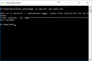


    The input file dem.tif is split into separate files with a numbered suffix starting from 0 e.g. split_0.tif.
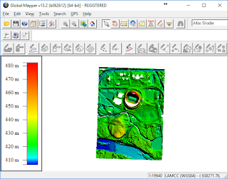
  2. Now, the file can be displayed properly in Global Mapper.
Monday, August 26, 2013

Retaining GeoTiff metadata for an image after editing in Photoshop

Sometimes for whatever reason, we have to edit a GeoTiff image in a photo manipulation software application like Photoshop. These image editing applications usually do not retain the geo-referencing information of the GeoTiff file after editing. The following screenshots show a GeoTiff image being edited in GIMP to remove some text from the image.

When the edited file is opened in a mapping software application e.g. Global Mapper, the software will be unable to detect any geo-referencing information, as shown below.


There is a way to apply back the geo-referencing information from the original GeoTiff file. As long as the edited image pixel sizes (width and height) remain the same as the original GeoTiff image, we can copy the GeoTiff metadata from the original file to the edited file using the listgeo and geotifcp executables. These programs can be downloaded as part of FWTools.

The following shows how to use the listgeo and geotifcp executables.

  1. Open up a command prompt. Type in the following:

    C:\> listgeo -no_norm original.tif > metadata.geo

    The GeoTiff file's geo-referencing metadata is copied out from the input original.tif and written to the output file metadata.geo.
  2. Next, type in the following:

    C:\> geotifcp -g metadata.geo edited.tif output.tif

    The geo-referencing info in the metadata.geo file is applied to the edited.tif file and written out to output.tif.  When the output.tif file is loaded in a mapping application, the image is placed in the correct geographic location.


Monday, April 8, 2013

Add text label as attribute to polygon in Global Mapper

It is useful to be able to copy the text label from points (so called area centroids) to the enclosing area polygons as attributes. This can be done using Global Mapper's Add Attributes to Selected Areas from Points command. If the text labels are not already point attributes, then there is a simple workaround that can be performed to convert them into point attributes. The following example illustrates the workaround by simply exporting out the points as a Shapefile and using the exported Shapefile for the source point attributes.

  1. In Global Mapper, create, load and display the area polygons and points with labels.


  2. Select File | Export Vector Format.

    The Select Export Format dialog box appears.

  3. Choose Shapefile. Click OK.

    The Shapefile Export Options appear.

  4. Toggle on Export Points. Specify the destination point Shapefile name and location, e.g. C:\Temp\centroid.shp.


  5. Click OK.

    The point Shapefile is created.
  6. Unload the original point layer.


  7. Drag and drop the exported point Shapefile, e.g. centroid.shp, onto the Global Mapper's map view.
  8. Press ALT+P. Click on one of the points.

    The Feature Information dialog box appears.

    Note: the text label is an attribute
    .
  9. Press ALT+D. Click and drag to select all the area polygons and points.


  10. Press right click on the mouse.

    A popup menu appears.


  11. Choose Attribute Functions | Add Attributes to Selected Areas from Points.

    A prompt appears.

  12. Click Yes.

    A message appears.

  13. Click OK.

    The text label is added to the area polygons as attributes.

Monday, November 12, 2012

Copy point database attributes to polygons in Global Mapper

A common task in GIS is to copy the attributes of points to the enclosing area polygons. It is simple to perform the task in Global Mapper as illustrated below.

  1. Start Global Mapper. Load a polygon layer and a point layer.

  2. Press ALT+D.

    The Digitizer tool is activated.
  3. Click and drag a rectangle around the polygons and points.

    The polygons and points are selected.
  4. Press the mouse right button anywhere in the map view.

    A pop up menu appears.
  5. Select Attribute Functions | Add attributes to Selected Areas from Points.

    The following message appear.
  6. Click Yes. Then click OK.

    The point attributes are copied to the polygons.

Monday, October 29, 2012

Add coordinate attributes to points in Global Mapper

Sometimes for whatever reason it is useful to convert the point geometry X and Y vertices as database attributes so that they can be manipulated just like any other database attributes. It is simple to do this in Global Mapper. This is illustrated in the example below.

  1. Start Global Mapper. Load in a point geometry layer.

  2. Optional. Select Tools | Feature Info. Click on any point.

    The Feature Information dialog box appears.

    Note: there are no database attribute fields for the vertices.
  3. Select Tools | Digitizer.

    The digitizer tool is activated and the cursor becomes a cross-hair with the label EDIT.
  4. Click and drag a rectangle to select one or more points.

    The selected points are highlighted in red.


  5. Press the mouse right button.

    A pop up menu appears.

  6. Choose Attribute Functions | Add coordinate attributes to selected points.

    The X,Y coordinates are added to the point attributes. A message box appears.


  7. Close the message box.
  8. Optional. Select Tools | Feature Info. Click on one of the points.

    The Feature Information dialog box appears.

    Note: the X,Y coordinate attribute fields are now displayed.

Monday, October 8, 2012

Calculate the difference between ground control points and a DEM using Global Mapper

Somebody asked me how to find out the elevation difference between the digital elevation model (DEM) and independently surveyed ground control points (GCP). Any terrain software such as Global Mapper should have the tools to calculate the differences. In this post, I shall illustrate the steps to use Global Mapper to find out the elevation differences.

It is not as straightforward as other software as there is no single tool in Global Mapper. Basically, the DEM and the ground control points layer must be loaded together first; then the DEM elevation under the control point must be added to the GCP layer as an ELEVATION database attribute field. With the database attributes having the GCP elevation and DEM elevation fields, a database field subtraction can be done to calculate the difference between the DEM elevation and the GCP elevation.

Load the DEM and GCPs

  1. Start Global Mapper. Load in a DEM layer e.g. dtm.asc.


  2. Load and display the vector GCP layer e.g. gcp.shp.

  3. Optional. Select Search | Search by Attributes, Names, and Description.

    The Search by Attributes, Names, and Description dialog box appears.

    Note the GCP elevation field e.g. GPS_ELEVAT

Append the DEM elevation to the GCP
  1. Select File | Export Vector Format.

    The Select Export Format dialog box appears.
  2. Choose a format e.g. Shapefile. Click OK.

    The Shapefile Export Options dialog box appears.
  3. Toggle on Generate 3D Features Using Loaded Elevation data.
  4. Toggle on Export Points.

    The Save As dialog box appears.
  5. Type in the new GCP layer name e.g. gcp_dsm_accuracy.shp. Click Save.


    The GCP layer is exported out to a new vector file. The DEM elevation for each GCP point is appended to the output file
    .
  6. Press ALT+C.

    The Overlay Control Center dialog box appears.
  7. Select the loaded GCP layer e.g. gcp.shp. Click Close Overlay.

    The GCP layer is unloaded
    .

Calculate the difference between GCP and DEM elevations
  1. Load in the GCP layer appended with the DEM elevations exported previously e.g. gcp_dsm_accuracy.shp.

  2. Press ALT_C.

    The Overlay Control Center appears.

  3. Right click on the GCP layer.

    A pop up menu appears.

  4. Choose CALC_ATTR.

    The Setup Attribute Calculation dialog box appears.
  5. In the Select Existing or Create New Attribute to Assign Calculated Values to field, type in a name e.g. hgtdiff.
  6. In the Source Attribute field, choose the GCP elevation field, e.g GPS_ELEVAT.
  7. In the Operation field, choose Subtract.
  8. Toggle on Use Attribute Value. Choose the DEM elevation field e.g. ELEVATION.


  9. Click OK.

    The differences are calculated and inserted into the hgtdiff field.


    The Feature Information dialog box below shows the new field with the calculated difference for one of the GCP feature.

Monday, September 10, 2012

Swipe the display of raster images on and off in Global Mapper 13

Global Mapper 13 comes with a new Image Swipe Tool which as the name suggests, will swipe the display of an image on and off. As long as one or more raster layer displayed, the command can be activated. The following illustrates how the command can be used.

  1. Start Global Mapper. Load and display 2 raster layers e.g. an OpenStreetMap layer and a SRTM Worldwide Elevation Data layer.

  2. Select Tools | Image Swipe Tool.

    The Select Layer to Swipe dialog box appears.


  3. Choose the raster layer to swipe on and off. Usually this should be the uppermost layer. Click OK.

    The cursor changes to a white cross.
  4. Move the cursor to the center of the map display. Press down the left mouse button and move the cursor left or right.

    The selected raster layer display is swiped on or off at the cursor point.

Monday, February 13, 2012

Simple canopy height derivation using Global Mapper

The forest canopy height is the height of the highest vegetation above the ground level. It is possible to calculate the canopy height from LiDAR derived digital terrain models (DTM) and digital surface models (DSM) gridded datasets by doing a simple subtraction in Global Mapper. The example below shows how to use the Combine Terrain Layers function in Global Mapper to calculate the canopy height.

  1. Start up Global Mapper. Load in a digital terrain model ESRI ArcGrid file e.g. dtm.asc.

  2. Load in a digital surface model ESRI ArcGrid file e.g. dsm.asc.

  3. Select File | Combine Terrain Layers.

    The Combine Terrain Options dialog box appears.
  4. In the Description field, type in relevant text e.g. CanopyHeight.
  5. In the Operation field, choose Subtraction (Difference) - Signed.
  6. In the Select First Elevation Layer to Combine field, choose the DSM layer e.g. dsm.asc.
  7. In the Select Elevation Layer to Combine the First Layer With field, choose the DTM layer e.g. dtm.asc.

  8. Click OK.
  9. Press CTRL+C. Toggle off the DTM and DSM layers.

    The canopy height is displayed as shown below where the pink indicates zero canopy heights and the blues are positive heights.