Showing posts with label Data Editing. Show all posts

Monday, October 24, 2022

QGIS unable to edit SpatiaLite database layer workaround

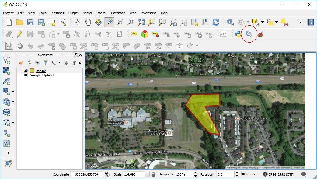
Recently I upgraded to QGIS 3.26 on Ubuntu 22.04 and found that I was unable to edit my existing SpatiaLite database layers, i.e. the Toggle Editing tool bar icon could not be enabled. The screenshot below illustrates the problem.

While I have not found the cause of the problem, I found a simple workaround to the issue: just create a new SpatiaLite database and import the layers from the old database. The newly imported database layers can be enabled for editing. 


Create a new SpatiaLite database

  1. In the Browser pane of QGIS, press the right mouse button on the SpatiaLite node.


    A pop up menu appear.

  2. Choose Create New Database.


  3. In the Name field, type in a new SpatiaLite database file name, e.g. new_rail.sqlite. Click Save.

    The database is created.


Import layers from the old SpatiaLite database to the new SpatiaLite database

  1. If the layer e.g. node from the old SpatiaLite database e.g. rail.sqlite is not displayed in QGIS, then add the layer to the map window.


  2. In the QGIS menu, select Database | DB Manager.

    The DB Manager dialog box appears.


  3. Expand the SpatiaLite Providers tree node and double click on the newly created SpatiaLite database, e.g. new_rail.sqlite.


  4. Click Import Layer/File.

    The Import vector layer dialog box appears.


  5. In the Input drop down list, choose the layer from the old database, e.g. nodes. In the Output Table field, type in a new table name, e.g. nodes. Click OK.

    The old layer is imported into the new database.

Displaying the newly imported Spatialite layer

  1. In QGIS, select Layer | Add Layer | Add SpatiaLite Layer.


  2. In the Connections drop down list, select the new SpatiaLite database, e.g. new_rail.sqlite. Click Connect.

  3. In the table list, select the new layer nodes. Click Add.

    The new nodes layer is displayed in the map window.


  4. Select the new layer nodes in the Legend pane.

    The Toggle Editing icon is enabled now.


Monday, May 21, 2018

Perform a 2D geo-registration of a LiDAR LAS file to a GeoTiff image with Cloud Compare

Recently I received LiDAR LAS point clouds generated without using accurate GPS positioning. As a result, the data is not placed at the correct geographic location in the world. To rectify this, I used Cloud Compare to so-called geo-register the point clouds to the world using GeoTiff images as reference.

The following illustrates how it was done:

Load the GeoTiff image as reference
  1. Start Cloud Compare.


  2. Select File | Open.

    The Open file(s) dialog box appears.

  3. Browse and select the reference GeoTiff raster file, e.g. autzen.tif. Click Open.

    The Result type prompt appears.

  4. Click No to load as a texture map instead of converting to a point cloud.

    The Global shift/scale dialog box appears.

  5. Accept the defaults. Click Yes.

    The GeoTiff image is loaded.
Load the LAS file
  1. Select File | Open.


  2. Browse and choose the LAS file, e.g. autzen.las. Click Open.

    The Open LAS File dialog box appears.
  3. Click Apply.

    The Global shift/scale dialog box appears.

  4. Click Yes to accept the defaults.

    The LAS file is loaded.
 Setup the display
  1. In the vertical tool bar on the left, click the Set Current View Mode icon
    and choose Orthographic projection.

    Note: we do not want the perspective projection display to mislead us as to the location of the features
  2. Optional. Select Edit | Colors | Height Ramp. Click OK in the Gradient color dialog box to display the point cloud with a height color gradient for better visualization.


Perform the rectification
  1.  In the DB Tree pane, select the point cloud to rectify, e.g. autzen.las.
  2. In the top tool bar, click the Translate/Rotate icon .

    The Translate/Rotate widget appears in the top right corner.
  3. In the Rotation field, select Z. Toggle off Tz.

    Note: we only want to move horizontally in the 2D plane.
  4. Look for matching features in the point cloud and the GeoTiff image.


  5. To translate the point cloud, press down the mouse right button and drag the point cloud to the new location. To rotate the point cloud, press down the mouse left button and rotate the point cloud.

    Note 1: To toggle the display of the point cloud, toggle on/off the Visible property in the Properties pane on the left.
    Note 2: To zoom in/out/pane around, pause the Translate/Rotate widget by clicking the widget's Pause icon.
  6. In the Translate/Rotate widget, click the Tick icon to save the changes.

    The point cloud is rectified.


Wednesday, July 12, 2017

Applying a simple X,Y shift or translation to a raster GeoTIFF file using GDAL

Sometimes when comparing a raster ortho-mosaic GeoTIFF file to ground control points (GCPs), the raster file may appear to be slightly shifted relative to the ground control points. To resolve this problem correctly, it may be necessary to regenerate the ortho-mosaic after adjusting the tie points. But sometimes, if the shift is linear or you want to do a fast correction, then the open source software GDAL may be able to solve the problem for you.

To shift a raster GeoTIFF file e.g. input.tif with GDAL, do the following:

  1. Open up a Windows Command Prompt.
  2. Type in the gdal_translate command with the a_ullr option:

    C:\> gdal_translate -a_ullr 760726.437 4557390.415 772996.466 4540826.364 input.tif translate.tif

    Note: 
    translate.tif is the output filename
    -a_ullr specifies the new upper left X, upper left Y, lower right X, lower right Y coordinates  

  3. Run the command.

    Processing messages appear. The file is shifted to the new coordinates.


    The file is shifted to the new coordinates.

Wednesday, June 28, 2017

Mask a LAS file using PDAL and QGIS

The Point Data Abstraction Library (PDAL) comes with a useful function to mask or crop out a LiDAR LAS file with one or more polygons. The example screenshot below shows a point cloud overlaid with a red polygon in the upper right corner, which outlines the desired area of the point cloud to be cropped.

The cropping can be done using PDAL's crop filter but it requires the cropping polygon to be specified in the Well Known Text (WKT) string format. This is a bit of pain but can be overcome using a few methods, one of which is shown below using QGIS and the Plain Geometry Editor plugin.

Define the cropping polygon
  1. In QGIS, draw a new polygon e.g. mask, as shown below.


    Note: The mask should be created in the same coordinate system as the LAS file
  2. Click the Plain Geometry Editor icon in the toolbar (red circle above). Click on the clipping polygon.

    The Plain Geometry Editor dialog box appears.


    Note: Install the Plain Geometry Editor plugin if the icon is not available.
  3. In the text field, select and copy all the polygon WKT text string into the Windows clipboard.  
Create a PDAL processing pipeline JSON file
  1. In a text editor, type in something similar to the example below.
  2. From the Windows Clipboard, paste the WKT string from the previous section to the "polygon" attribute and surround it with double quote '"' characters.
  3. Save the JSON file e.g. process.json.
{
  "pipeline":[
    "autzen.laz",
    {
      "type":"filters.crop",
      "polygon": "Polygon ((638500.66904077248182148 853359.34703735215589404, 638869.71793351718224585 853365.15883093187585473, 638881.34152069012634456 853208.24040409235749394, 638677.92874516302254051 853199.52271371346432716, 638878.43562390014994889 852818.85023379256017506, 638733.14078423334285617 852842.09740813483949751, 638611.09311891463585198 852975.76866063219495118, 638416.39803376235067844 853211.14630088687408715, 638500.66904077248182148 853359.34703735215589404))"
    },
    {
      "type":"writers.las",
      "filename":"file-cropped.las"
    }
  ]
}

Note: 
  • The pipeline JSON file stores the processes to be done in sequence in an array bracketed by the '[' and ']' characters. 
  • autzen.laz is the input LAS file for this example
  • filters.crop is the process to apply using the "polygon" attribute.
  • file-cropped.las is the output LAS file. 


Run the cropping process
  1. Open up the OSGeo4W Shell.
  2. At the prompt, type in the pdal pipeline command:

    C:\> pdal pipeline process.json -v 4
    Processing messages appear. The file is cropped.

  3. Optional. Using your preferred LAS Viewer, open up the resultant cropped LAS file.

    The cropped file showing only the cropped area is displayed.


Monday, May 22, 2017

Merging multiple comma separated values CSV files

If there are many comma separated value CSV files with headers and you want to merge them into a single CSV file, it can be a pain having to do it by hand. Fortunately, there are ways to automate the task. One method which I like is to use the tail command from Unix. For Windows, a tail utility can be downloaded from http://tailforwin32.sourceforge.net/;There are others which a Google search can reveal.

Below are screenshots of a few CSV files to merge.


  1. Using a text editor, create a script or batch file. In the editor, type in the tail command to create a new merged file with a header.

    tail -n +1 -q green.csv > merge.csv

    Note: -n +1 means to start from the first line.
    A single > means to output to a new file

  2. Type in the commands to append lines from subsequent files without headers to the output file.

    tail -n +2 -q orange.csv >> merge.csv
    tail -n +2 -q transfer.csv >> merge.csv
    #...etc...
    Note: -n +2 means to start from the 2nd line
    >> means to append to the output file

  3. Run the script or batch file in a Command Prompt.

    The CSV files are merged.

Monday, November 3, 2014

Convert MultiLineString geometries to LineString using SpatiaLite SQL

Recently I made a mistake in creating a linear feature as a multi-line string instead of a plain line string geometry in SpatiaLite. I really did not want to digitize the features again so I decided to use SQL statements to convert the existing multi-line string geometries to line strings.

The following simple example shows how to do the conversion from a multi-line string table roads to a new line string table newroads. The basic steps involve (1) creating a new table, (2) populate the new table, (3) updating the new table with the line string geometry, (4) fixing the spatial metadata.
The table roads with the incorrect Multi-Line String geometry

Create a new table

  1. In SpatiaLite, type in the following SQL statement to create a new empty table newroads from the roads table. Execute the statement.

    CREATE TABLE newroads AS SELECT * FROM roads LIMIT 0

    A blank table is created with the same structure as the roads table.

Populate the new table with the textual attribute values
  1. In SpatiaLite, type in the following SQL statement to copy the rows (without the geometry field) from the original roads table into the new table newroads.

    INSERT INTO newroads(pkuid,name)SELECT pkuid,name FROM roads 
  2. Execute the SQL statement.

    All the rows are copied into the new table newroads.

    A simple query of the new table newroads show that all fields are populated with the exception of the geometry field, which remains as null.


Update the geometry field
  1. In SpatiaLite, type in the following SQL statement to form the SQL update statements to populate the geometry field.

    SELECT
    'UPDATE newroads SET Geometry='||'ST_GeomFromText('''||
    AsText(Geometry)||
    ''', 4326) WHERE pkuid='||
    pkuid||';' FROM roads


    Note: 4326 is the coordinate system reference used for the roads feature.
  2. Execute the statement.

    The update SQL statements are generated.

  3. In SpatiaLite GUI, click the grey area above and left of the resultant rows, as shown above.

    All the resultant rows are selected.
  4. Mouse right click on the selected rows.

    A pop up menu appears.

  5. Choose Copy.

    The resultant rows are copied to the OS Clipboard.
  6. In a text editor, paste the rows into a new file, e.g. demorun.sql.


  7. Change all occurrences of the string "MULTILINESTRING" to "LINESTRING".
  8. Change all occurrences of the string "((" to "(".
  9. Change all occurrences of the string "))" to ")".

    The statements should now look like the following example.

    UPDATE newroads SET Geometry=ST_GeomFromText('LINESTRING(-123.013367 49.328037, -122.980708 49.353917, -122.981324 49.386576, -122.975779 49.409992)', 4326) WHERE pkuid=1;
  10. Save the changes.
  11. In SpatiaLite, click the Execute SQL script button as shown below.


    The SQL Script Windows appears.

  12. Select the newly created SQL script file, e.g. demorun.sql. Click Open.

    The geometry field in newroads is updated.


Fix the spatial metadata
  1. In SpatiaLite GUI, mouse right click on the geometry field of the new table newroads.

    A pop up menu appears.

  2. Choose Recover geometry column.

    The Recover geometry column dialog box appears.
  3. In the SRID field, type in the coordinate system SRID value e.g. 4326.
  4. In the Dims field, choose the appropriate dimension of the geometry field, e.g. XY.
  5. In the Geometry Type list, choose LINESTRING.
  6. Click OK.

    The geometry field is recovered.