FME can be used to write Intergraph Framme linkages. The tricky part is not actually writing the linkages to the graphic DGN elements but figuring out what values to write to the Framme linkages. If you somehow have the correct values from somewhere, then you can use either the FME Workbench or write a FME mapping file to create the linkages.
In this example below, I created an FME mapping file to create DGN line elements with Framme linkages from geometries in a PostGis database table named pipeline. The work is done at the Transformation section of the mapping file as shown in bold below. I am assuming that I have the proper values already calculated and stored as attributes in the PostGis table.
#======================================================================== # Transformation section #======================================================================== POSTGIS pipeline \
postgis_type postgis_line \
i_level %igds_level \
i_color %igds_color \
i_style %igds_style \
i_weight %igds_weight \
i_group %igds_graphic_group \
i_class %igds_class \
ufid %ufid \
feat_num %feat_num \
state_num %state_num \
comp_num %comp_num \
comp_count %comp_count \
dgnfile %dgnfile \
the_geom %geom
IGDS level \
igds_type igds_line \
igds_level %igds_level \
igds_color %igds_color \
igds_style %igds_style \
igds_weight %igds_weight \
igds_graphic_group %igds_graphic_group \
igds_class %igds_class \
geom %geom \
igds_linkage{0}.type framme \
igds_linkage{0}.ufid %ufid \
igds_linkage{0}.feature_num %feat_num \
igds_linkage{0}.state_num %state_num \
igds_linkage{0}.component_num %comp_num \
igds_linkage{0}.comp_count %comp_count \
igds_linkage{0}.design_file %dgnfile

About Geospatial Applications, FME, Visual Studio, gvSIG, Global Mapper, Programming, LiDAR, GIS, Google Maps, SAGA GIS, Android, QGIS
Thursday, December 18, 2008
Create DGN Elements on Correct Levels with FME
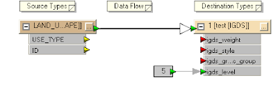
By default, if you use the FME Workbench or the FME Universal Translator to create a DGN file, the geometries will be created as DGN graphic elements on level 1 and above incrementally for each feature type. For example as shown in the workbench figure below, the destination of my source feature is set to level 1, as indicated with the text "1" in the title bar.
Most times, users will want to control and define the output levels of the output DGN graphic elements since levels is a useful way to organize the graphical data e.g. level 1 for vegetation land use, level 2 for park land use, etc.
In this posting, I describe a way using FME mapping file to define and control the destination level. I am assuming that I have an attribute in the source feature that stores the level number.
- Use the FME Universal Translator to generate a mapping file from your source format e.g. ESRI Shape to the destination MicroStation Design format.

- Use a text editor to open up the resultant mapping file e.g. mapping.fme.
The mapping file may look like this.
# ============================================================================
# Source feature type definition section
# ============================================================================
SHAPE_DEF LAND_USE \
SHAPE_GEOMETRY shape_polygon \
USE_TYPE char(50) \
IGDS_LEVEL number(10,0) \
ID number(10,0)
# ============================================================================
# Transformation section
# ============================================================================
SHAPE LAND_USE \
USE_TYPE %USE_TYPE \
ID %ID
IGDS 1 \
igds_type igds_solid \
USE_TYPE %USE_TYPE \
ID %ID - In the Transformation section for the source format, add in the following line in bold.
SHAPE LAND_USE \
USE_TYPE %USE_TYPE \
IGDS_LEVEL %IGDS_LEVEL \
ID %ID - In the Transformation section for the destination IGDS format, replace the number "1" with the text "level" and add in the following line in bold.
Note: igds_level must be in lower case.
IGDS level \
igds_type igds_solid \
USE_TYPE %USE_TYPE \
igds_level %IGDS_LEVEL \
ID %ID - Save the changes and close the mapping file. Now when you run the translation, the DGN graphic elements will be created in the level defined in the IGDS_LEVEL attribute of the source feature.

Wednesday, November 26, 2008
Calculating Polygon Centroids in GeoMedia
GeoMedia's Functional Attributes or Update Attributes commands can be used to calculate the centroid of polygon geometries. For instance, in the screen shot below, I have two polygon geometries that I want to calculate the centroid coordinates and I want to store the values as database attributes associated with the geometries.
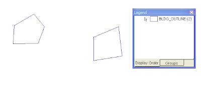
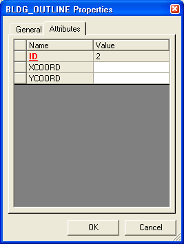
At the moment, the polygon geometries' database attributes are blank as shown below.
The steps are as follows:

At the moment, the polygon geometries' database attributes are blank as shown below.

The steps are as follows:
- In GeoMedia, select Edit > Attribute > Update Attributes.
The Update Attributes dialog box appears. - In the Update features in box, expand your read/write connection node and select the polygon feature you want to update e.g. BLDG_OUTLINE.
The Update Attributes dialog box may look like this.
- Click the cursor on the attribute field you want to update with the polygon geometries' centroid X coordinate e.g. XCOORD.
- Click Expression.
The Expression dialog box appears. - In the Expression field, type in the following string:
X(CENTERPOINT(Input.Geometry), Constant.ProjectedMeas, Constant.METER))
Note: Replace Input.Geometry with the name of your geometry field. The RefSpace argument can be either Constant.ProjectedMeas or Constant.TrueMeas. The UnitOfMeasure argument can be angular units (if Constant.TrueMeas is used) or linear units like Constant.METER, Constant.INCH, etc.
The Expression dialog box may look like this.
- Click OK.
- Repeat the steps 3 to 7 for the Y coord field. The expression string for the Y coord may look like this:
Y(CENTERPOINT(Input.Geometry), Constant.ProjectedMeas, Constant.METER))
At the end, the Update Attributes dialog box may look like this.
- Click Apply.
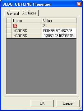
The centroids of the polygon geometries are calculated and updated into the attribute fields. - Click Close.


Monday, November 10, 2008
Use Google Maps to create Pin Maps
Prior to Google Maps, either you use a paper map and stick some pins on it to mark locations or you could buy some mapping software like MapInfo, ArcView to do the job; on top of that you had to buy some map data from somebody and that could burn a big hole in your pocket. But Google Maps provide you with some decent pin mapping capabilities for free with reasonable looking maps.
- To start, open up your favorite browser and go to http://maps.google.com. You should click on the My Maps link.
You should see a page like this.
- Click Create new map.
- If you like, in the Title field type in a meaningful map title, e.g. PinMap, and a description.

Note: Toggle Unlisted on if you do not want to share the map to everybody. - In the Google Map canvas, navigate to the location you want to place a pin.
Note: You can use the Search Maps function to locate places by street address if you wish. For example, I can type in '38 Jalan Ikan Merah, Singapore' in the search entry field and click the button as shown below.
The geocoded location is displayed.

- Click the Add a Placemark button at the top of the map canvas (the icon that looks like a reverse tear drop).
The cursor becomes to a cross hair marker and you are prompted to "click to place me on the map".
- Click a point on the map canvas.
The Info balloon pops up.
- In the Title field, type in a meaningful name, e.g. Pin1 and enter a description if necessary. Note that you can change the icon from the default if you wish here.
- Click OK.
- Repeat steps 4-8 to place more pins.
- When all pins have been placed, the page may look like this.

- That's it, you're done. You can create and display more than one layers of pins if you wish. If you made a mistake, simply click on the pin and choose Delete to remove the pin.


Friday, November 7, 2008
R.S.O. Borneo (M) Projection Conversion Calculator

To convert lat/lon coordinates to easting/northing coordinates, simply type in the lat/lon coordinates below and click Convert to Easting, Northing.
Equations for the coordinate conversions are from this site.
Tuesday, November 4, 2008
Creating your own toolbar in GeoMedia
You can create your own toolbar in GeoMedia. In fact, it is even necessary to create your own toolbar sometimes - for instance, when debugging your custom command there is a useful Unload Command that you can use to unload your custom command from the GeoMedia application process so that you can recompile and overwrite your dll. This command is not exposed out on the GeoMedia menus or toolbars.
Here are the steps to create your own toolbar.
Sometimes you want to remove a few buttons or even remove the toolbar entirely. Here are the steps to do that.
Here are the steps to create your own toolbar.
- Open up a workspace in GeoMedia.
- Select Tools > Customize.
The Customize dialog box appears. - In the Categories list box, click on a category, e.g. Development Tools.
The icons for the selected category appear in the Buttons group box.
- In the Buttons group box, click and drag out a command icon as shown in the figure below.

- Repeat steps 3 to 4 for additional command buttons you want to add to your toolbar. The additional buttons will have to be dropped onto your toolbar as shown in the figure below.

- When you are done adding, click Close to exit.


Sometimes you want to remove a few buttons or even remove the toolbar entirely. Here are the steps to do that.
- On the keyboard, press the ALT key and hold it down.
- With the mouse, left click on the button you want to remove and drag out from the toolbar as shown in the figure below.

The resultant toolbar looks like this.


Thursday, October 30, 2008
New Geocoding Engine in GeoMedia 6.1
I am pleased to find out that version 6.1 of Intergraph's line of GeoMedia products including GeoMedia, GeoMedia Professional, WebMap and WebMap Professional have a new address geocoding engine. In previous versions, I could only perform address geocoding with WebMap Location Server which uses the Annotated Centerline Engine (ACE) - that is still available in 6.1 for backward compatibility. The problem with this is that in this region, addresses are better located with postal codes that are tied to so-called address points, not left and right of centerlines. But 6.1 allows geocoding on both point and linear reference data. That means, I can use it here! Yeah.
Tuesday, October 28, 2008
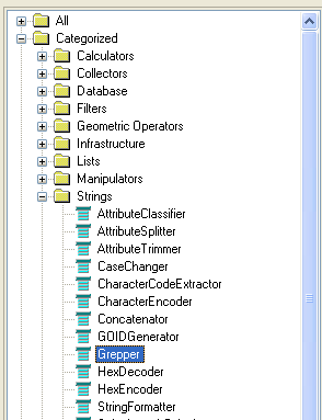
Using the FME GREPPER Factory
Instead of using the typical FME Workbench factories for filtering records by attributes e.g. AttributeFilter, AttributeClassifier or Tester factories, you could use a powerful regular expression processing factory - the Grepper. As the name suggests, it performs a Unix 'grep' like operation on the input attributes. This factory is available under the Strings category of the FME Workbench as shown in the screen shot below.
The screen shot below shows a typical usage of the Grepper factory in the FME Workbench.
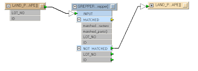
In the example above, the records from LAND_PARCELS feature are filtered through the GREPPER factory. Any unmatched records will be output to the new LAND_PARCELS feature; any matched records to the GREPPER's regular expression will be ignored.
Display the GREPPER's parameters to set the regular expression as shown below.
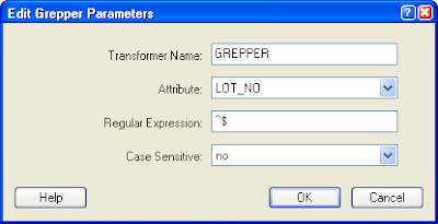
You will have to click the Attribute field and choose an attribute to grep or filter against with the regular expression. In the example above, the field LOT_NO was chosen.
Find Null Strings
If you want to find matches for null strings, i.e. strings with just carriage returns or line feeds, then define the Regular Expression '^$' as shown in the example screen shot above. In plain English, the carat character '^' anchors the expression to the beginning of the string while the dollar '$' character anchors the expression to the end of the string; put together with nothing in between, the expression says 'match all strings with nothing from start to the end of the string'.
Find Strings that Begin with a Character
If you want to find matches for strings that begin with a character such as 'N', then define the Regular Expression '^N'. Some matching strings include the following:
NO12-12345
Nobody
Find Strings that Match a Pattern
The following Regular Expression 'NO\d\d-\d\d\d\d\d' will match any strings with the pattern NOxx-xxxxx where x is any numeric character. Some examples of matching strings include the following:
NO12-12345
Hello World NO12-12345 Hello World
Find Null Numeric Values
The Grepper can be used on numeric fields such as double or integer fields. FME will do a string conversion first before passing the value to the Grepper factory. If you want to filter out any null values in double or integer database fields, you can define the Regular Expression '^$'.
Wednesday, October 22, 2008
Convert Latitude/Longitude to Easting/Northing Coordinates
The CoordSystem object in GeoMedia can perform among other things, coordinate conversion from latitude and longitude to easting and northing using its TransformPoint method. What is not clear from the GeoMedia Object Reference developer documentation is that the latitude and longitude coordinates must be passed in as radians, not degrees; there was no mention of the units at all. I was at a loss for a while wondering why the converted values were incorrect until I found some example code from the Intergraph web site showing the correct usage. In fact, there is also a UnitAndFormatSpec object that comes with the Coordinate System Services (PCSS) that can help you perform the latitude, longitude conversion to radians. Example C# code listing is shown below.
PCSS.CoordSystemsMgr coordSysMgr = null;
PCSS.CoordSystem coordSys = null;
PCSS.UnitAndFormatSpec spec = null;
bool isValid = false;
double x = 104.0, y = 4.0, z = 0.0;
double[] point = { 0, 0, 0 }; //the output easting, northing, height values

//Get a reference to the Coordinate Systems Manager class
//of the GeoMedia workspace
coordSysMgr = (PCSS.CoordSystemsMgr) this._document.CoordSystemsMgr;

//Create an instance of the UnitAndFormatSpec class
spec = (PCSS.UnitAndFormatSpec)this._application.CreateService("UnitAndFormatSpec");

//Convert the longitude to radians
spec.ParseValueString(Intergraph.GeoMedia.PCSS.CSValueStringConstants.csvsLongitude, lng.ToString(), out x);

//Convert the latitude to radians
spec.ParseValueString(Intergraph.GeoMedia.PCSS.CSValueStringConstants.csvsLatitude, lat.ToString(), out y);

//Get a reference to the coordinate system class
coordSys = coordSysMgr.CoordSystem;

//Check first to see if the conversion from latitude, longitude to
// easting, northing is valid
coordSys.IsTransformationValid(Intergraph.GeoMedia.PCSS.CSPointConstants.cspLLU, 1, Intergraph.GeoMedia.PCSS.CSPointConstants.cspENU, 1, out isValid);

//If the conversion is valid, then perform the actual conversion
//from latitude, longitude to easting, northing.
if (isValid == true)
{
   coordSys.TransformPoint(Intergraph.GeoMedia.PCSS.CSPointConstants.cspLLU, 1, Intergraph.GeoMedia.PCSS.CSPointConstants.cspENU, 1, ref x, ref y, ref z);
   point[0] = x;
   point[1] = y;
   point[2] = z;
}
Monday, October 20, 2008
Quick Display of DXF Files in GeoMedia 6.x
By design, the Display CAD Files command in GeoMedia allows you to quickly and easily display CAD files without having to go through the process of defining the CAD Server Schema file; it is difficult for casual users to set up a CAD Server Schema without having much knowledge about the structure and organization of the data in the CAD files. In previous versions, the Display CAD Files command could only handle Microstation design files. But it looks like the command has been enhanced to be able to display AutoCAD DWG/DXF files quickly in version 6.x. So now, AutoCAD users can celebrate!
To start,
If you don't like the compound geometries the command is setting for all the DXF layers or you want to refine the settings made by the Display CAD Files command, then you can modify the CAD Server Schema file generated by the command. Before you can do that, you have to close all open connections to the CAD Server Schema file first.
To start,
- In GeoMedia, select Tools > Display CAD Files.
The Display CAD Files dialog box is displayed.
- In the CAD type drop down list, select AutoCAD.
- In the CAD files folder field, type in or click Browse to define the folder containing your DXF files, e.g. D:\Warehouses\dxf\.
Available DXF files are displayed in the Available files list box.
- In the Available files field, checked on one or more DXF files.
- If you want to associate a coordinate system file for your DXF file(s), then in the Coordinate system file field, type in or click Browse to define the coordinate system file, e.g. D:\Warehouses\dxf\TransverseMercator.csf (optional).
The Display CAD Files dialog box may look like this.
Note: If a coordinate system file is not defined, then GeoMedia will assume the DXF coordinates are in the current workspace's coordinate system. - Click the Advanced tab.
The advanced options are displayed.
- In the Generated CAD server schema file field, type in or click Browse to define the CAD server schema file to be generated, e.g. D:\Warehouses\landuse_dxf.csd. Note: this is optional and you can use the default name if you like.
- In the Connection name field, type in a name, e.g. DXF connection. Note: This is optional and you can use the default name if you like.
- Toggle on Select layers to display. Note: selecting this option will cause the command to scan the DXF file for the layer names. This is preferable to having to figure out by yourself.
The list of DXF layer names is displayed in the Layers list box.
- Toggle on Create a separate legend entry for each selected layer. Note: this is optional but preferable to displaying all DXF graphics as a single GeoMedia feature.

- Click OK.
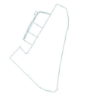
The selected DXF layer is displayed in the Map Window as a compound geometry.


If you don't like the compound geometries the command is setting for all the DXF layers or you want to refine the settings made by the Display CAD Files command, then you can modify the CAD Server Schema file generated by the command. Before you can do that, you have to close all open connections to the CAD Server Schema file first.
- In Windows Explorer, browse to the CAD Server Schema File folder e.g. D:\Warehouses\ and double click on the CAD Server Schema File, e.g. landuse_dxf.csd.
The Define CAD Server Schema File dialog box appears.
- Select Feature Class > Define Feature Class.
The Define Feature Class dialog box appears.
- In the Feature classes list box, select a feature class, e.g. LAND_USE. Click Edit.
The Edit - Feature XXX dialog box appears.
- In the Geometry type list box, toggle off the CompoundGeometry and TextGeometry. Toggle on the desired type, e.g. AreaGeometry.

- Click OK.
- Click Close.
- Select File > Save.
- Select File > Exit to close the Define CAD Server Schema File application.
- Open up GeoMedia and display the DXF layers.
The DXF feature now has the geometry type of AreaGeometry.


Tuesday, October 14, 2008
Fine tuning of the GeoMedia MapWindow object's height and width
Sometimes I need to define the exact width and height of the GeoMedia map in pixels to control the dimensions of the map view image created by the snap shot function. To do this, a developer can create a custom program to access the MapWindow object and set the width and height properties, as follows:
However, this is not entirely correct because the width and height of the MapWindow object include the Windows border and title bar as shown in the example screen shot below.
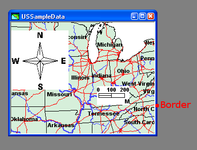
When you do a snap shot of the map window by selecting Edit > Snapshot, an image of the map view is created in the Windows clipboard. The map view image would have a width and height a little less than the width and height you set earlier e.g. 504 pixels by 489 pixels.
To get a map view image with the exact dimensions you want, you will have to add the border width and title bar height to the MapWindow object's width and height properties. An example code listing is shown below.
mapWnd.Width = 512;
mapWnd.Height = 512;
However, this is not entirely correct because the width and height of the MapWindow object include the Windows border and title bar as shown in the example screen shot below.

When you do a snap shot of the map window by selecting Edit > Snapshot, an image of the map view is created in the Windows clipboard. The map view image would have a width and height a little less than the width and height you set earlier e.g. 504 pixels by 489 pixels.
To get a map view image with the exact dimensions you want, you will have to add the border width and title bar height to the MapWindow object's width and height properties. An example code listing is shown below.
MapviewLib.GMMapView mview = null;
double xlo = 0, ylo = 0, zlo = 0, xhi = 0, yhi = 0, zhi = 0; //world
int pixelXlo = 0, pixelYlo = 0, pixelXhi = 0, pixelYhi = 0; //pixels
int mviewWidth, mviewHeight;   //map view dimensions

//Set an initial desired width and height, e.g. 512x512
mapWnd.Width = 512;
mapWnd.Height = 512;

//Get the mapview object in the map window
mview = (MapviewLib.GMMapView)mapWnd.MapView;

//Get the map view object's MBR in real world coordinates
mview.GetRange(ref xlo, ref ylo, ref zlo, ref xhi, ref yhi, ref zhi);

//Convert the real world coordinates to screen pixels
mview.WorldToWindow(xlo, ylo, zlo, ref pixelXlo, ref pixelYlo);
mview.WorldToWindow(xhi, yhi, zhi, ref pixelXhi, ref pixelYhi);

//Calculate the map view objects width and height
mviewWidth = Math.Abs(pixelXhi - pixelXlo);
mviewHeight = Math.Abs(pixelYhi - pixelYlo);

//Adjust the map window object's dimensions by adding
//in the border and title bar's dimensions
mapWnd.Width = (mapWnd.Width - mviewWidth) + mapWnd.Width;
mapWnd.Height = (mapWnd.Height - mviewHeight) + mapWnd.Height;

After this adjustment, the snap shot image will have the correct desired dimensions.
Tuesday, September 30, 2008
Accessing DXF Files in GeoMedia
Before you can display any DXF layers or features in GeoMedia, you have to create and define a CAD Server Schema file. This schema file simply defines a collection of DXF files within the DXF warehouse, and all the DXF layers/features within the DXF files. You must classify the DXF graphics as GIS features/layers based on some unique classification criteria such as the DXF EntityColor, LayerName etc. For instance, you may have created AutoCAD polygons representing land use boundaries on a layer named as 'LANDUSE'. If so, you can define a classification criteria that states that all entities on the DXF layer 'LANDUSE' are LandUse features.
Here are the steps to create the schema file and to connect to the DXF warehouse.
Defining the CAD Server Schema File
You can now connect to the DXF file via the CAD Server Schema in GeoMedia.
Here are the steps to create the schema file and to connect to the DXF warehouse.
Defining the CAD Server Schema File
- On the Windows desktop, select Start > All Programs > GeoMedia > Utilities > Define CAD Server Schema File.
The Define CAD Server Schema File dialog box appears.
- In the Define CAD Server Schema File dialog box, select File > New.
The New dialog box appears.
- Choose AutoCadTemplate.csd and click New.
The Select Map Files dialog box appears.
- In the Select Map Files dialog box, click New.
The Browse For Folder dialog box appears. - Browse and choose the folder containing your DXF file(s), e.g. D:\Warehouses\dxf\. Click OK.
The Select Map Files dialog box displays the selected folder and any DXF files contained in the folder.
- In the Map files list box, toggle on the DXF file(s). Click OK when done.
The Select Coordinate System Files dialog box appears.
- In the Coordinate system files list box, toggle on the coordinate system file suitable for the DXF data. Click OK.
Note: Prior to this step, you must have created and defined a suitable coordinate system file using the GeoMedia Define Coordinate System File utility.
The Define Feature Class dialog box appears.
- In the Define Feature Class dialog box, click New.
The New dialog box appears. - In the Name field, type in a suitable name for a feature in the DXF data, e.g. LandParcel.
- In the Geometry type list box, toggle on an appropriate geometry type for the feature, e.g. AreaGeometry.
The New dialog box may look like this.
- Click the Graphic Attributes tab.
- Toggle on any Graphic Attribute Name you wish to expose as attributes in GeoMedia, e.g. EntityColor, BlockName, EntityType, etc.

- Click the Criteria tab.
- Toggle on the DXF Attribute Name(s) that defines the current feature and type in the Classification Criteria.
For example, if you have polygons representing land parcels in the DXF file and they are stored uniquely on a DXF layer named as 'LAND_PARCELS', then you would toggle on the LayerName attribute and typed in LAND_PARCELS in the Classification Criteria field.
- Click OK.
The Define Feature Class displays the newly defined DXF feature.
- If you have additional features to define, repeat the previous steps 8 to 15.
- In the Define Feature Class dialog box, click Close.
- In the Define CAD Server Schema File dialog box, select File > Save.
The Save As dialog box appears.
- In the File name field, type in a name for the new CAD Schema definition file, e.g. Dxf.csd.
- Click Save.
- Close the Define CAD Server Schema File dialog box.


You can now connect to the DXF file via the CAD Server Schema in GeoMedia.
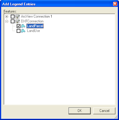
- In GeoMedia, select Warehouse > New Connection.
The New Connection dialog box appears.
- In the Connection type list box, select CAD.
- In the Connection name field, type in an appropriate name, e.g. DXFConnection.
- In the CAD Server Schema file field, click Browse and select the schema file you created earlier.
- Click OK.
GeoMedia is now connected to the DXF data warehouse.


Subscribe to:
Posts (Atom)
