Monday, December 9, 2019

Fix error 400 bad request when trying to use create-react-app

While attempting to create a new ReactJS app with the create-react-app tool, I encountered the following error: "error 400 Bad Request: run-async@^2.2.0". See the screenshot below.

After some research, I found the node npm cache could be corrupted. So running the following command fixed the issue for me.

$ npm cache verify


The create-react-app tool now can complete successfully, as shown below:
$ npx create-react-app myapp


Monday, November 18, 2019

Fix USB serial adapters to static device names on Ubuntu

When a USB to serial device adapter are plugged into a computer's USB port, the Ubuntu Linux OS automatically assigns a default system device name to it. Typically, it is /dev/ttyUSB0, /dev/ttyUSB1, and so on. This is convenient but sometimes it may be necessary to fix a specific device name to a specific USB serial adapter. This can be done by defining a rule file as shown in the steps below.

Identify the USB serial adapter's product and vendor codes
  1. Open up a Terminal. Physically plug in the USB serial adapter to the computer's USB port. Type in the following command:

    $ dmesg | grep ttyUSB
    The device messages with the string ttyUSB are displayed.

  2. Note which default device name has been assigned. In this case it is /dev/ttyUSB0.

  3. Type in the following command to print out the attributes of the device.

    $ udevadm info --name=/dev/ttyUSB0 --attribute-walk

    The attributes are printed out.

  4. Scroll and look for the idProduct and idVendor attributes.


  5. Note down the codes for the idProduct and idVendor attributes. In this case, the codes are ea60 and 10c4 respectively.
Define a rule to rename the USB serial adapter device
  1. In a text editor, create a rule file e.g. 50-usb-serial.rules. Type in the following line:

    SUBSYSTEM=="tty", ATTRS{idVendor}=="10c4", ATTRS{idProduct}=="ea60", SYMLINK+="my_device_name"

    Note: replace the idVendor and idProduct and the my_device_name with the appropriate values.

    An example file listing:

  2. Place the rule file in /etc/udev/rules.d/. Note: you need to place it as the super user.
Activate the rule
  1. This can be done by restarting the computer.
  2. Alternatively, run the following command in a Terminal:

    $ sudo udevadm trigger
  3. To see whether it has been renamed, type in the following command:

    $ ls -l /dev/my_device_name

    Note: replace my_device_name with the name you defined in the rule file.

    The USB serial device has been renamed accordingly as a symbolic link.

Monday, November 11, 2019

Android Studio: Automatically replace the Google Maps V2 API Key for debug and release mode

The Android Google Maps API requires a separate debug and release keys in the Android Studio project's AndroidManifest.xml file, as shown in the listing below.

<meta-data
android:name="com.google.android.maps.v2.API_KEY"
android:value="your_google_maps_v2_api_debug_or_release_key_here" />
It can get tedious having to replace the key every time you want to debug or to generate a release build APK.

It is possible to use Gradle to automate the replacement of the Google Maps V2 API key value by using constants defined in the Gradle build types. To automate the replacement, you can do the following:
  1. In the Android app's build.gradle file, add in the following line under the debug component of buildTypes:

    resValue "string", "google_maps_v2_api_key", "your_google_maps_v2_debug_api_key_here"

    Note: replace the api key accordingly; and the constant name is google_maps_v2_api_key.
  2. Similarly, add in the following line under the release component of buildTypes:

    resValue "string", "google_maps_v2_api_key", "your_google_maps_v2_release_api_key_here"
  3. The Android app's build.gradle should look like this screenshot below:


  4. Now, in the app's AndroidManifest.xml file, replace the Google Maps V2 API key metadata value to the string constant name google_maps_v2_api_key.

    <meta-data
    android:name="com.google.android.maps.v2.API_KEY"
    android:value="@string/google_maps_v2_api_key" />
    

Now you can debug or build the Android app as per normal without manually replacing the Google Maps V2 API key.

Monday, November 4, 2019

Fixing the git-credential-osxkeychain password prompts on every git transaction

After a password change in my gitlab account, sometimes the git-credential-osxkeychain password prompt (shown below) will always pop up whenever I try to perform a git commit transaction on my Macbook.

And it seemingly will not allow you to proceed even though the correct password has been entered; only by pressing the ESC key will MacOSX allow the transaction to go through.

To resolve this issue, the following steps can be done:
  1. Press Command + spacebar on the keyboard to bring up the Finder. Type in keychain. Press Enter.

    The Keychain access dialog box appears.
  2. In the Search field, type in gitlab.

    The list is filtered by the search string.
  3. Now, mouse right click on the gitlab entry on the list. Choose Delete "gitlab.com".

    The keychain entry is deleted.
The gitlab keychain entry will be regenerated the next time and the git-credential-osxkeychain prompt will no longer pop up.

Monday, October 28, 2019

Android Studio: resolving duplicate AndroidX and support classes errors

While migrating an Android project from the support libraries to use the AndroidX libraries, I encountered the following errors regarding "duplicate class android.support.v4.app xxxx found in modules classes.jar (androidx.core:core:1.0.0) and classes.jar (com.android.support:support-compat:26.1.0)"; even though all the Java/Kotlin/XML source code files have been replaced with the AndroidX versions and the old support libraries have been removed from the app's build.gradle file.

The screenshot below illustrates the error.


The solution I found was to set project wide gradle properties.
  1. In Android Studio, open up the project's gradle.properties file.
  2. Insert the following two lines:

    android.enableJetifier=true
    android.useAndroidX=true


  3. Save the file, select Build | Clean Project. Then select recompile again.

    The duplicate classes error messages no longer appear.|

Monday, October 21, 2019

Setting and passing ROS double array parameters to a ROS C++ node

I tried to pass an array or list of double parameters to a ROS node program through the ROS rosrun program but my C++ ROS node program could not read the double array parameter. For example, the screenshot below shows the command to run a ROS node (hello_doubles) from the package beginner_tutorials and setting my_doubles_array parameter with the double list [1.1, 2.2, 3.3]:

$ rosrun beginner_tutorials hello_doubles _my_doubles_array:="[1.1,2.2,3.3]"

Note that after running the command, the ROS parameter server contains a parameter /hello_doubles/my_doubles_array with a string value of '[1.1, 2.2., 3.3]' and not the expected double array [1.1, 2.2, 3.3].

Eventually, I realized the rosrun program passes the list as a string instead of an array of doubles. In order to pass a double array parameter, the following methods could be used instead: (1) use the rosparam set command, or (2) use the rosparam load command.

Use the rosparam set command to pass a double array parameter
  1. In a Terminal, type in the following command:

    $ rosparam set /hello_doubles/my_double_array "[1.1, 2.2, 3.3]"

Use the rosparam load command to set a double array parameter
  1. Using a text editor, create a yaml file e.g. hello_doubles.yaml with the following lines:


    where my_doubles_array is the name of the double array parameter
  2. In a Terminal, type in the following command to load the yaml file:

    $ rosparam load /path/to/hello_doubles.yaml

Monday, October 14, 2019

Simple example of a ReactJS and OpenLayers map component

OpenLayers (https://openlayers.org/) is a "high-performance, feature-packed (Javascript) library for all your mapping needs" for web sites. I spent some time figuring out how to use it with ReactJS. As most of the available examples in the official documentation are for plain vanilla HTML/Javascript, I stumbled a few times trying to get it to work. This post summarises the steps to get a minimal OpenLayers - React component to work. 


Installing OpenLayers for ReactJS
Assuming a ReactJS project has been created e.g. /path/to/React/project/, the first thing is to install the prerequisite software.
  1. Install OpenLayers package for node. Open a Terminal, change directory to the project root directory and type in the following command.

    $ npm install ol --save
  2. Optional. Install Proj4Js and Material-UI.

    $ npm install proj4 @material-ui/core --save
Create the React component for OpenLayers map
Under the ReactJS project e.g. /path/to/React/project/src/components/, create the OpenLayers React component e.g. OLMapFragment.js.

Code listing of OLMapFragment.js
import React from 'react'
import Grid from '@material-ui/core/Grid'

// Start Openlayers imports
import { 
    Map,
    View
 } from 'ol'
import {
    GeoJSON,
    XYZ
} from 'ol/format'
import {
    Tile as TileLayer,
    Vector as VectorLayer
} from 'ol/layer'
import {
    Vector as VectorSource,
    OSM as OSMSource,
    XYZ as XYZSource,
    TileWMS as TileWMSSource
} from 'ol/source'
import {
    Select as SelectInteraction,
    defaults as DefaultInteractions
} from 'ol/interaction'
import { 
    Attribution,
    ScaleLine,
    ZoomSlider,
    Zoom,
    Rotate,
    MousePosition,
    OverviewMap,
    defaults as DefaultControls
} from 'ol/control'
import {
    Style,
    Fill as FillStyle,
    RegularShape as RegularShapeStyle,
    Stroke as StrokeStyle
} from 'ol/style'

import { 
    Projection,
    get as getProjection
 } from 'ol/proj'

// End Openlayers imports

class OLMapFragment extends React.Component {
    constructor(props) {
        super(props)
        this.updateDimensions = this.updateDimensions.bind(this)
    }
    updateDimensions(){
        const h = window.innerWidth >= 992 ? window.innerHeight : 400
        this.setState({height: h})
    }
    componentWillMount(){
        window.addEventListener('resize', this.updateDimensions)
        this.updateDimensions()
    }
    componentDidMount(){

        // Create an Openlayer Map instance with two tile layers
        const map = new Map({
            //  Display the map in the div with the id of map
            target: 'map',
            layers: [
                new TileLayer({
                    source: new XYZSource({
                        url: 'https://{a-c}.tile.openstreetmap.org/{z}/{x}/{y}.png',
                        projection: 'EPSG:3857'
                    })
                }),
                new TileLayer({
                    source: new TileWMSSource({
                        url: 'https://ahocevar.com/geoserver/wms',
                        params: {
                            layers: 'topp:states',
                            'TILED': true,
                        },
                        projection: 'EPSG:4326'
                    }),
                    name: 'USA'
                }),
            ],
            // Add in the following map controls
            controls: DefaultControls().extend([
                new ZoomSlider(),
                new MousePosition(),
                new ScaleLine(),
                new OverviewMap()
            ]),
            // Render the tile layers in a map view with a Mercator projection
            view: new View({
                projection: 'EPSG:3857',
                center: [0, 0],
                zoom: 2
            })
        })
    }
    componentWillUnmount(){
        window.removeEventListener('resize', this.updateDimensions)
    }
    render(){
        const style = {
            width: '100%',
            height:this.state.height,
            backgroundColor: '#cccccc',
        }
        return (
            <Grid container>
                <Grid item xs={12}>
                    <div id='map' style={style} >
                    </div>
                </Grid>
            </Grid>
        )
    }
}
export default OLMapFragment

Use the React OpenLayers map component
Now in the ReactJS project's index.js file under /path/to/React/project/src/, import in the newly created OLMapFragment component and render it.

Listing of index.js
import React from 'react'
import { render} from 'react-dom'
import OLMapFragment from './js/components/OLMapFragment'

render(
    <OLMapFragment />
    ,
    document.getElementById('react-container')
)

Create the default index.html file
Finally, include links to OpenLayer's style sheets in the project's index.html file under /path/to/React/project/src/.
Listing of index.html file
<!DOCTYPE html>
<html class="no-js" lang="en">

<head>
    <meta charset="utf-8">
    <meta http-equiv="x-ua-compatible" content='ie=edge'>
    <title>Openlayers React</title>
    <meta name="description" content="Explore planet Mars">
    <meta name="viewport" content="minimum-scale=1, initial-scale=1, width=device-width, shrink-to-fit=no" />
    <!-- material-ui prerequisites -->
    <link rel="stylesheet" href="https://fonts.googleapis.com/css?family=Roboto:300,400,500,700&display=swap" />
    <link rel="stylesheet" href="https://fonts.googleapis.com/icon?family=Material+Icons" />
    <!-- end material-ui prerequisites -->

    <link rel="stylesheet" href="https://cdn.rawgit.com/openlayers/openlayers.github.io/master/en/v5.3.0/css/ol.css"
        type="text/css" />

</head>

<body>
    <!--[if lte IE 8]
        <p class="chromeframe">You are using an <strong>outdated</strong> browser. Please <a href="http://browsehappy.com">upgrade your browser</a></p>
        <![endif]-->
    <div id='react-container'></div>

</body>

</html>

Now, run the ReactJS project with a web server and open the web page with an Internet browser.

The web map tiles are rendered in the React OpenLayers component.

Monday, October 7, 2019

Add Mars Web Mapping Tile Server datasets from NASA to QGIS

NASA publishes Mars dataset such as the Viking Color Mosaic or the Mars Orbiter Laser Altimeter Color Hillshade  for public access at this web site https://api.nasa.gov/api.html. The dataset are published as OGC RESTful Web Mapping and Tile Services - hence they can be pulled down and displayed in QGIS.

For convenience, the full list of the dataset extracted from the service is shown below:
Layer Url
Viking Color Mosaic - Global Map https://api.nasa.gov/mars-wmts/catalog/Mars_Viking_MDIM21_ClrMosaic_global_232m/1.0.0//default/default028mm/{z}/{y}/{x}.jpg
CTX Mosaic - Curiosity Landing Site https://api.nasa.gov/mars-wmts/catalog/curiosity_ctx_mosaic/1.0.0//default/default028mm/{z}/{y}/{x}.png
HiRISE Mosaic - Curiosity Landing Site https://api.nasa.gov/mars-wmts/catalog/curiosity_hirise_mosaic/1.0.0//default/default028mm/{z}/{y}/{x}.png
HiRISE Mosaic - ESP_040776_2115 https://api.nasa.gov/mars-wmts/catalog/ESP_040776_2115_RED_A_01_ORTHO/1.0.0//default/default028mm/{z}/{y}/{x}.png
HiRISE Mosaic - ESP_042252_1930_RED_B_01_ORTHO https://api.nasa.gov/mars-wmts/catalog/ESP_042252_1930_RED_B_01_ORTHO/1.0.0//default/default028mm/{z}/{y}/{x}.png
HiRISE Mosaic - ESP_042647_1760_RED_B_01_ORTHO https://api.nasa.gov/mars-wmts/catalog/ESP_042647_1760_RED_B_01_ORTHO/1.0.0//default/default028mm/{z}/{y}/{x}.png
HRSC Mosaic - Martian East https://api.nasa.gov/mars-wmts/catalog/HRSC_Martian_east/1.0.0//default/default028mm/{z}/{y}/{x}.png
HRSC Color Mosaic - MC11 https://api.nasa.gov/mars-wmts/catalog/MC11E_HRMOSCO_COL/1.0.0//default/default028mm/{z}/{y}/{x}.png
HRSC Mosaic - MC11 https://api.nasa.gov/mars-wmts/catalog/MC11E_HRMOSND_ND5/1.0.0//default/default028mm/{z}/{y}/{x}.png
HiRISE Mosaic - Spirit Landing Site https://api.nasa.gov/mars-wmts/catalog/spirit_hirise_mosaic/1.0.0//default/default028mm/{z}/{y}/{x}.png
HiRISE Mosaic - Opportunity Landing Site https://api.nasa.gov/mars-wmts/catalog/opportunity_hirise_mosaic/1.0.0//default/default028mm/{z}/{y}/{x}.png
HiRISE Mosaic - Phoenix Landing Site https://api.nasa.gov/mars-wmts/catalog/phoenix_hirise_mosaic/1.0.0//default/default028mm/{z}/{y}/{x}.png
HiRISE Mosaic - Sojourner Landing Site https://api.nasa.gov/mars-wmts/catalog/sojourner_hirise_mosaic/1.0.0//default/default028mm/{z}/{y}/{x}.png
Albedo Mosaic - Thermal Emission Spectrometer https://api.nasa.gov/mars-wmts/catalog/Mars_MGS_TES_Albedo_mosaic_global_7410m/1.0.0//default/default028mm/{z}/{y}/{x}.png
DEM Grayscale - Mars Orbiter Laser Altimeter https://api.nasa.gov/mars-wmts/catalog/Mars_MGS_MOLA_DEM_mosaic_global_463m_8/1.0.0//default/default028mm/{z}/{y}/{x}.png
Color Hillshade - Mars Orbiter Laser Altimeter https://api.nasa.gov/mars-wmts/catalog/Mars_MGS_MOLA_ClrShade_merge_global_463m/1.0.0//default/default028mm/{z}/{y}/{x}.jpg
Experience Curiosity - Curiosity Landing Site https://api.nasa.gov/mars-wmts/catalog/mars_pahrump_patch_8k_256m/1.0.0//default/default028mm/{z}/{y}/{x}.png
Atlas Mosaic - Mars Orbiter Camera https://api.nasa.gov/mars-wmts/catalog/msss_atlas_simp_clon/1.0.0//default/default028mm/{z}/{y}/{x}.png
Infrared Night - Thermal Emission Imaging System https://api.nasa.gov/mars-wmts/catalog/Mars_MO_THEMIS-IR-Night_mosaic_60N60S_100m_v14_clon0_ly/1.0.0//default/default028mm/{z}/{y}/{x}.jpg
Infrared Day - Thermal Emission Imaging System https://api.nasa.gov/mars-wmts/catalog/Mars_MO_THEMIS-IR-Day_mosaic_global_100m_v12_clon0_ly/1.0.0//default/default028mm/{z}/{y}/{x}.jpg
HRSC Mosaic - Mawrth Vallis https://api.nasa.gov/mars-wmts/catalog/hrsc_mawrth_vallis/1.0.0//default/default028mm/{z}/{y}/{x}.png
HRSC Color Mosaic - Mawrth Vallis https://api.nasa.gov/mars-wmts/catalog/hrsc_mawrth_vallis_color/1.0.0//default/default028mm/{z}/{y}/{x}.png

To add a MARS dataset to QGIS, do the following:
  1. Start QGIS. In the Browser panel, mouse right click on the Tile Server (XYZ). Select New Connection.


  2.  In the New XYZ tile layer, type in the URL for the chosen dataset, e.g. https://api.nasa.gov/mars-wmts/catalog/Mars_MGS_MOLA_ClrShade_merge_global_463m/1.0.0//default/default028mm/{z}/{y}/{x}.jpg

  3. Click OK.
  4. Type in the name of the tile layer, e.g. Color Hillshade - Mars Orbiter Laser Altimeter.

  5. Click OK.

    The tile layer connection is added to the Tile Server (XYZ) node.
  6. Mouse right click on the newly added tile server node. Choose Add layer.

    The selected layer is displayed in QGIS.

Monday, September 30, 2019

CMake example for cross compiling and using a static library for a Raspberry Pi on an Ubuntu PC

Compiling source code on a Raspberry Pi can be sluggish compared to a PC. So instead I decided that cross compilation on an Ubuntu PC would be faster and therefore more productive of my time. So after a few false starts, I finally managed to get the workflow working. This post shows a simple example of how to compile a C++ static library and using that in an executable for Raspberry Pi using the CMake build system on an Ubuntu PC.

Down the Raspberry Pi build tools
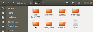
The first thing is to get the Raspberry cross compilation tools from the git repository.

In Ubuntu, open a Terminal. Type in the following to download the tools to a folder e.g. /path/to/programs/pi/.

$ cd ~/programs/pi/
$ git clone https://github.com/raspberrypi/tools.git


Create a CMake toolchain file
Next, create a cmake file e.g. /path/to/workspace/toolchain-rpi.cmake specifying the correct Raspberry cross compilation tools for compiling C/C++ source files with the CMAKE_C_COMPILER and CMAKE_CXX_COMPILER macros. Also the root folder of the Raspberry Pi libraries and include files need to be specified with the CMAKE_FIND_ROOT_PATH macro.

Choose the right ones for your Raspberry Pi chipset.

Listing of toolchain-rpi.cmake
SET(CMAKE_SYSTEM_NAME Linux)
SET(CMAKE_SYSTEM_VERSION 1)

# define the C cross compiler for the Raspberry Pi 
SET(CMAKE_C_COMPILER $ENV{HOME}/programs/pi/tools/arm-bcm2708/arm-rpi-4.9.3-linux-gnueabihf/bin/arm-linux-gnueabihf-gcc)

# define the C++ cross compiler for the Raspberry Pi
SET(CMAKE_CXX_COMPILER $ENV{HOME}/programs/pi/tools/arm-bcm2708/arm-rpi-4.9.3-linux-gnueabihf/bin/arm-linux-gnueabihf-g++)

# define the root location of the Raspberry Pi libraries and includes
SET(CMAKE_FIND_ROOT_PATH $ENV{HOME}/programs/pi/tools/arm-bcm2708/arm-linux-gnueabihf/arm-linux-gnueabihf/sysroot)

SET(CMAKE_FIND_ROOT_PATH_MODE_PROGRAM NEVER)
SET(CMAKE_FIND_ROOT_PATH_MODE_LIBRARY ONLY)
SET(CMAKE_FIND_ROOT_PATH_MODE_INCLUDE ONLY)

add_definitions(-Wall -std=c11)

Create the workspace
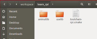
In the same example project workspace folder /path/to/workspace/, create two folders animallib and uselib, the first for the library files, and the later for the executable files.


Create the static library
The next step is to create the header file and define the classes that will be used by the example executable. Place the Animal.h and Animal.cpp files respectively in the include and src folders under the /path/to/workspace/animallb/ folder.

Listing of Animal.h
#include <string>

using namespace std;

class Animal {
        private:
                string name;
        public:
                Animal(string);
                virtual void print_name();
};

Listing of Animal.cpp
#include <iostream>
#include "Animal.h"

using namespace std;

Animal::Animal(string name): name (name) {}

void Animal::print_name(){
        cout << "Name is " << this->name << endl;
}

Create the static library's CMakeLists.txt file in the animallib folder e.g. /path/to/workspace/animallib/. As defined, this will help to generate a static library libanimallib.a and a header file animallib_Export.h.

cmake_minimum_required(VERSION 2.8.6)
project (animallib)

set (BUILD_SHARED_LIBS OFF)
set (CMAKE_BUILD_TYPE Debug)

#include *.h files under the include folder and
#the project's output folder e.g. build
include_directories (include ${PROJECT_BINARY_DIR})

#compile all *.cpp source files under the src folder
file (GLOB SOURCES "src/*.cpp")

#output static library export file *.a and
#output macro definitions include file
include (GenerateExportHeader)
add_library(animallib STATIC ${SOURCES})
GENERATE_EXPORT_HEADER (animallib
        BASE_NAME animallib
        EXPORT_MACRO_NAME animallib_EXPORT
        EXPORT_FILE_NAME animallib_Export.h
        STATIC_DEFINE animallib_BUILT_AS_STATIC
        )

Open up a Terminal and change directory to the static library's folder e.g. /path/to/workspace/animallib/.

If the build folder does not exist, create it.

$ mkdir build
$ cd build

Type in the cmake command with the CMAKE_TOOLCHAIN_FILE variable pointing to the previously created Raspberry Pi toolchain CMake file.

$ cmake -D CMAKE_TOOLCHAIN_FILE=/path/to/workspace/toolchain-rpi.cmake ..

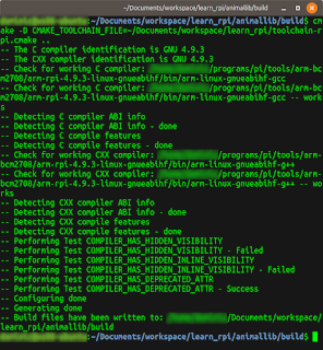
Build files are generated


In the Terminal, type in the make command to generate the static library file.
$ make
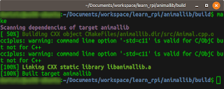
Static library compilation messages
Using the static library in a separate C++ application
Now that the library has been generated, the next thing is to use the library's classes and functions in an executable e.g. uselib project under /path/to/workspace/uselib/.

Listing of uselib.cpp
#include "Animal.h"

#include "animallib_Export.h"

int main(int argc, char *argv[]){
        Animal animal("Dog");
        animal.print_name();
        return (0);
}

Place the source code file uselib.cpp under the src directory e.g. /path/to/workspace/uselib/src/.

Then create a CMakeLists.txt file under the /path/to/workspace/uselib/ folder.
cmake_minimum_required(VERSION 2.8.6)
project (UseLib)

# link as a static library
set(CMAKE_EXE_LINKER_FLAGS "-static")

set (EXAMPLE_DIR $ENV{HOME}/Documents/workspace/learn_rpi/)

# name and location of the library to link with the executable
set (PROJECT_LINK_LIBS animallib)
link_directories (${EXAMPLE_DIR}/animallib/build/)

include_directories (
        ${EXAMPLE_DIR}/animallib/include
        ${EXAMPLE_DIR}/animallib/build
        )

#compile all *.cpp source files under src folder
file (GLOB SOURCES "src/*.cpp")

#output executable name as uselib
add_executable (uselib ${SOURCES})
target_link_libraries (uselib ${PROJECT_LINK_LIBS})

Open up a Terminal. Change directory to the /path/to/workspace/uselib/ folder.

If the build directory does not exist, type in the following to create it.

$ mkdir build

Type in the cmake command with the CMAKE_TOOLCHAIN_FILE variable pointing to the previously created Raspberry Pi toolchain CMake file.

$ cmake -D CMAKE_TOOLCHAIN_FILE=/path/to/workspace/toolchain-rpi.cmake ..

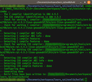
The build files are generated
Compile the executable with the make command.
$ make

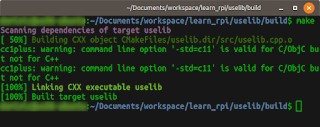
Compilation messages
Once the executable uselib has been generated, it can be copied to the Raspberry Pi and run. If you have an arm emulator e.g. qemu installed on the Ubuntu PC, then it can be executed as shown below.
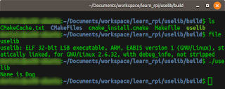
Running the Raspberry Pi executable on the Ubuntu PC with QEMU

Monday, September 23, 2019

Installing Vim-youcompleteme for Ubuntu 18.04

Modern text editors in IDE such as Visual Studio comes with a useful feature so-called Intellisense or automatic text completion. The venerable vi text editor can also have this feature enabled by installing and configuring suitable plug-ins such as vim-youcompleteme. I thought it might be fun using this and found a lot of methods to get it installed and running on Ubuntu 18.04, including fiddling with the .vimrc file. But the simplest way I found was to simply do the following:
  1. In a Terminal, run the command:

    $ sudo apt install vim-youcompleteme
  2. Next, run the command:

    $ vim-addon-manager install youcompleteme
Now, when editing a code file, vi will pop up an auto-completion list as you type, as shown in the screenshot below.

Monday, September 16, 2019

Allocating more space to an emulated Raspbian disk image

The Raspberry Pi Raspbian images from http://downloads.raspberrypi.org/raspbian/images/ for QEMU have limited disk space, just enough for booting up and not much else. In the screenshot below, the image has just 3.3GB to it.

In order to work with ROS or other applications, the disk image has to be resized with more free disk space. This can be done by doing the following.
  1. Optional but recommended. Make a copy of the original Raspbian image and rename it, for example as raspbian.img.

    $ cp 2019-06-20-raspbian-buster.img raspbian.img
  2. Extend the copied image's size with the following command in the Terminal.

    $ qemu-img resize raspbian.img +6G


    Note: +6G means to extend the original size by 6 gigabytes
  3. Next, boot up the newly resized image with QEMU.

    $ qemu-system-arm -kernel kernel-qemu-4.4.34-jessie \
      -cpu arm1176 \
      -m 256 \
      -M versatilepb \
      -serial stdio \
      -append "root=/dev/sda2 rootfstype=ext4 rw" \
      -hda raspbian.img \
      -net nic \
      -net user,hostfwd=tcp::5022-:22 \
      -no-reboot


    The QEMU window appears.

  4. In the QEMU window, open up a Terminal.
  5. Enter the following commands to delete and create a new partition.

    $ sudo fdisk /dev/sda
  6. Print out the current partitions by entering p. Make a note of the starting offset of the second partition e.g. 540672.


  7. Delete the second partition by entering d followed by 2. Then recreate the second partition by entering c, n, p, 2, followed by the starting address noted from the previous steps e.g. 540672. Leave the signature alone when prompted.


  8. Now, reboot the emulated Raspbian OS.
  9. When QEMU has restarted the Raspbian OS, open a Terminal and enter the command to resize the file system.

    $ sudo resize2fs /dev/sda2

  10. To see the available disk space, enter the command:

    $ df -h

Monday, September 9, 2019

How to emulate a Raspbian OS in QEMU on Windows 10

I wanted to test out developing for a Raspberry Pi on a Windows 10 PC platform running an emulated Raspbian OS. After trying out a few methods to get  the emulator running, I settled on the following procedure.

Install QEMU for 64-bit Windows 10
  1. Go to the following web site https://www.qemu.org/download/ and download the latest QEMU installer for Windows 64bit.
  2. Run the installer.

    The QEMU executable files are installed, e.g. C:\Program Files\qemu\
Download a Linux kernel
  1. Go to the following web site https://github.com/dhruvvyas90/qemu-rpi-kernel and download a suitable kernel, e.g. kernel-qemu-4.4.34-jessie.
  2. Place the kernel file in a folder e.g. D:/Temp/raspbian/kernel-qemu-4.4.34-jessie
Download an Raspbian OS image
  1. Go to the following web site http://downloads.raspberrypi.org/raspbian/images/ and download the latest image e.g. 2019-06-20-raspbian-buster.zip
  2. Unzip the image file into a folder, e.g. D:/Temp/raspbian/2019-06-20-raspbian-buster.img

Create a Windows bat file
  1. Run a text editor.
  2. Type in the following lines.

    "c:\Program Files\qemu\qemu-system-arm.exe" ^
    -kernel kernel-qemu-4.4.34-jessie ^
    -cpu arm1176 ^
    -m 256 ^
    -M versatilepb ^
    -serial stdio ^
    -append "root=/dev/sda2 rootfstype=ext4 rw" ^
    -hda 2019-06-20-raspbian-buster.img ^
    -net nic ^
    -net user,hostfwd=tcp::5022-:22 ^
    -no-reboot


    Note: rename the kernel and image file names (in bold) to match the downloaded file names accordingly.

  3. Save as a bat file e.g. run_raspbian.bat and close the editor.
Run QEMU
  1. Open up a Command Prompt.
     
  2. Change directory to the folder containing the kernel and image files e.g. D:/Temp/raspbian.
  3. Type in the command:

    D:\> run_raspbian.bat


    The QEMU window appears running Raspbian OS

Monday, September 2, 2019

Resolving VeloView not displaying live sensor data from Velodyne Lidar sensors

This is a fairly common problem when running VeloView with a real Velodyne Lidar sensor on Windows - even though the sensor e.g. VLP-16 or HDL-32 are powered on and connected to the host computer, no live point cloud data is displayed in VeloView. All you get is a blank screen as shown below.


The probable reason is that the Windows Defender firewall is set to block VeloView from accessing the ports used by the Velodyne sensors. Normally, Windows will prompt whether to allow the program to access the ports on the first startup of the program. If you click no to the prompt, then Windows will never ask again. To enable the ports for VeloView, you will have to manually open the ports. The steps are shown below.

  1. Click the Windows Start button. Start typing "firewall with advanced...".

    A list of matches appear.


  2. Click on Windows Defender Firewall with Advanced Security.

    The Windows Defender Firewall with Advanced Security dialog box appears.

  3. Click on Inbound Rules. Scroll the list and look for entries with the name Veloview.


  4. For each Veloview entry, double click on it.

    The Veloview Properties appear.

  5. Toggle on Enabled. Choose Allow the Connection. Click OK. Repeat for each Veloview entry.

    The entry in the list should be marked with a green tick icon.

  6. Close the dialog.

    VeloView should be able to display the live data from the Velodyne sensor.

Monday, August 26, 2019

Creating faux square Android Navigation Drawer icons

The Navigation drawer widget in Android can display vector SVG icons, but if the vector icons are non-rectangular, Android will distort the dimensions to force them into squares. This can be seen in the screenshot of the Hawaii flag icon below.


It is possible to extend the drawer by code to display non-rectangular icons but I prefer to adjust the SVG icon instead. The way I did it was to change the page size to a square and then placing a transparent square box around the page. The following steps illustrate:

Change the page to a square
  1. Open up the SVG icon in Inkscape.


  2. Select File | Document Properties.


    1. Under the Page tab, change the Width and Height to be equal e.g. 1200 x 1200 px. Close the dialog box.

      The page display changes to a square.

  3. Using the Align and Distribute tools, align the graphics to the middle of the page.


Create a transparent square
  1.  Next, click the Create rectangles and squares (F4) icon. Place a stroke only, no-fill rectangle on the page.


  2. Change the width and height of the rectangle to match the page dimensions e.g. 1200 by 1200 px.


  3. Change the origin to the upper left corner of the page, e.g. X=0, Y=0.

  4. Open the Fill and stroke pane. Change the stroke opacity to low or zero opacity, e.g. 0.


  5. Save the file.
Import the SVG vector icon into an Android drawable icon
  1.  In Android Studio, right click on the /path/to/app/res/drawables folder and choose New | Vector Asset.


  2. Toggle on Local File (PNG, SVG). Choose the new SVG icon file from the previous section.
  3. Click Next. Click OK.

    The drawable is created.
Using this new icon, the Navigation drawer can now display the icon seemingly with the correct proportions, as shown below.