Showing posts with label CloudCompare. Show all posts

Monday, October 26, 2020

Using CloudCompare to determine a 3D rotation matrix's euler angles and vice versa

Working with 3D transformation matrices and Euler angles can be a little confusing with all that complex mathematical calculations. I found the Apply Transformation tool in CloudCompare to be useful in helping to calculate the Euler angles i.e. roll, pitch, and yaw given the transformation matrix, or vice versa. 

To use the tool the find the roll, pitch and yaw, you can do the following:

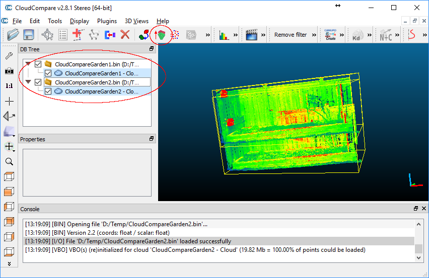
  1. Start up CloudCompare. Load a point cloud file and select it in the tree pane.


  2. Next, select Edit > Apply transformation.

    The Apply transformation dialog box appears.


  3. Type in the transformation matrix you want to determine the Euler angles.


  4. Then click the Euler angles tab.

    The calculated angles are displayed as Phi (yaw), Theta (pitch) and Psi(roll).

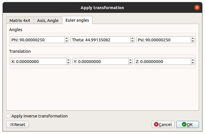
To determine the transformation matrix from the Euler angles, just type in the yaw, pitch, and roll values in the Phi, Theta and Psi fields. Then click the Matrix 4x4 tab. 

Monday, May 21, 2018

Perform a 2D geo-registration of a LiDAR LAS file to a GeoTiff image with Cloud Compare

Recently I received LiDAR LAS point clouds generated without using accurate GPS positioning. As a result, the data is not placed at the correct geographic location in the world. To rectify this, I used Cloud Compare to so-called geo-register the point clouds to the world using GeoTiff images as reference.

The following illustrates how it was done:

Load the GeoTiff image as reference
  1. Start Cloud Compare.


  2. Select File | Open.

    The Open file(s) dialog box appears.

  3. Browse and select the reference GeoTiff raster file, e.g. autzen.tif. Click Open.

    The Result type prompt appears.

  4. Click No to load as a texture map instead of converting to a point cloud.

    The Global shift/scale dialog box appears.

  5. Accept the defaults. Click Yes.

    The GeoTiff image is loaded.
Load the LAS file
  1. Select File | Open.


  2. Browse and choose the LAS file, e.g. autzen.las. Click Open.

    The Open LAS File dialog box appears.
  3. Click Apply.

    The Global shift/scale dialog box appears.

  4. Click Yes to accept the defaults.

    The LAS file is loaded.
 Setup the display
  1. In the vertical tool bar on the left, click the Set Current View Mode icon
    and choose Orthographic projection.

    Note: we do not want the perspective projection display to mislead us as to the location of the features
  2. Optional. Select Edit | Colors | Height Ramp. Click OK in the Gradient color dialog box to display the point cloud with a height color gradient for better visualization.


Perform the rectification
  1.  In the DB Tree pane, select the point cloud to rectify, e.g. autzen.las.
  2. In the top tool bar, click the Translate/Rotate icon .

    The Translate/Rotate widget appears in the top right corner.
  3. In the Rotation field, select Z. Toggle off Tz.

    Note: we only want to move horizontally in the 2D plane.
  4. Look for matching features in the point cloud and the GeoTiff image.


  5. To translate the point cloud, press down the mouse right button and drag the point cloud to the new location. To rotate the point cloud, press down the mouse left button and rotate the point cloud.

    Note 1: To toggle the display of the point cloud, toggle on/off the Visible property in the Properties pane on the left.
    Note 2: To zoom in/out/pane around, pause the Translate/Rotate widget by clicking the widget's Pause icon.
  6. In the Translate/Rotate widget, click the Tick icon to save the changes.

    The point cloud is rectified.


Monday, April 30, 2018

Better point cloud visualization in Cloud Compare with Eye Dome Lighting shading

Typically, LiDAR point clouds are displayed as a mass of colored points without perception of depth in a viewer. This can be hard to visualize objects or find your orientation in the point cloud. CloudCompare has a shading filter called the Eye Dome Lighting or EDL for short that can be used to apply a sort of depth outline around objects in the point cloud.

To use the EDL shader, do the following:
  1. In CloudCompare, load a point cloud file.

    The point cloud is displayed.
  2. Optional. To color the cloud, select the menu option Edit | Colors | Height Ramp.

    The Gradient color dialog box appears.


  3. Accept the default settings and click OK.

    The cloud is displayed with a default height ramp from blue (lowest) to red (highest).
  4. Now improve the display by applying the EDL Shader. In the menu, select Display | Shaders and Filters | E.D.L. (Shader).

    The shading is applied to the point cloud.

Thursday, March 23, 2017

LiDAR data coordinate readout in Cloud Compare

It is useful to obtain a readout of LiDAR data points in Cloud Compare, perhaps to determine the height value, or the intensity value of a LiDAR point. This post illustrates how to read out coordinate values in Cloud Compare.
  1. In Cloud Compare, load in a LAS file, e.g. Serpent Mound Model.las.

    The Global Shift/scale dialog box appears.


    Note: Real LiDAR data have large coordinate values requiring double data types, but most 3-D software like Cloud Compare works with coordinates in float data types internally. So in order to preserve the LiDAR coordinates in Cloud Compare, it may be necessary to apply some coordinate offset and/or scaling so that the LiDAR data points can fit into float data types. So when you load a LAS file in Cloud Compare, it will calculate and recommend an offset/scaling values before importing, as shown in the screen shot below.
  2. Click Yes.

    The LAS file is loaded; its data points are globally shifted and scaled.
  3. In the toolbar, click the Point picking icon.


    A point picking toolbar appears on the top right corner.
  4. By default, the first command (Select one point and displays its info) on the left is active. If not, click on it.
  5. Click on one LAS point.

    A balloon appears showing the X, Y, Z and a scalar value.

    Note: the xl, yl, zl on the left are local float data type coordinates. The xg, yg, zg on the right are the actual LiDAR data point vertices. The Point Source ID is the current scalar value.
If you want to get the read out to show another scalar field, you have to set the desired field before entering the Point Pick command, as described below.
  1. In the Tree pane, select the point cloud node, e.g. Serpent Mound Model.

    The Properties appear below the Tree pane.
  2. In the Scalar Fields | Active field, choose the desired field, e.g. Intensity.

    The point colors change to intensity values.
  3. Now, use the Point Pick command to readout a point.

    The readout balloon now shows the selected scalar field - Intensity.

Monday, March 6, 2017

Interactive cross-section in Cloud Compare

After loading LiDAR point clouds in Cloud Compare, it helps sometimes to cut a cross section or profile to get a feel for the land. There is a couple of Segment commands but the one I use for this purpose is the Cross Section Tool with the graphic interactors.

The following steps show how to use the Cross Section Tool.
  1. Load a point cloud file, e.g. Serpent Mound Model LAS Data.las, into Cloud Compare.
  2. Select the cloud in the DB Tree pane.


  3. Select Tools | Segmentation | Cross Section.


    The graphic interactors (the large 3D arrows pointing to the X, Y, Z axes) and Cross Section box appear
  4. Drag a cone of an interactor to thin the cross section box.

  5. Drag the torus of an interactor to rotate the cross section box.

  6. Adjust the interactors and camera view until the desired orientation is achieved.

    Note: if you wish to segment out the cross section into another cloud, click the Tick icon on the Cross Section tool box. Otherwise, click the X icon to exit the command when done.

Monday, February 27, 2017

How to enable Cloud Compare's Fine Registration (ICP) command

For the longest time, I tried to align two point clouds with CloudCompare's Fine Align (ICP) command. But unfortunately, the command would not enable for me no matter what I did. I selected one cloud, two cloud (or so I thought). Neither reading the documentation nor watching the YouTube videos helped. The screenshot below showed the deactivated Fine Align command in the tool bar.

It turned out that proper selection is key. I was using the SHIFT key to select one cloud folder node and another cloud folder node, which selected folders, and clouds among other things.

  1. The proper way was to press down the CTRL key while clicking on only cloud nodes in the tree view pane, as shown in the screenshot below. Once two cloud nodes have been selected, the File Align icon in the toolbar will become enabled.

    The File Align icon is enabled.
    he 
  2. Click the Fine Align icon.

    The Clouds registration dialog box appears.


Monday, June 10, 2013

Display LiDAR LAS file in Cloud Compare

Cloud Compare, a 3-D point cloud and mesh processing open source software can be used to display LiDAR LAS files. Being a generic point cloud processing software, it has the tools to manipulate the point clouds including filtering by point scalar values e.g. LAS classification, editing, mesh creation, among other functions. The following steps demonstrate displaying a LAS file's ground points as a point cloud as well as a 3-D surface mesh.

  1. Start Cloud Compare.

    The CloudCompare application window appears.

  2. Select File | Open.

    The Open file(s) dialog box appears.

  3. Browse and select a LAS lidar point cloud (*.las, *.laz) file e.g. lub_tile1.las. Click Open.

    The LAS file point cloud is displayed. In this example, the blue points are ground points while the red points are the vegetation points.

  4. With the mouse, click and drag anywhere within the graphic view. Roll the mouse wheel forward or backward to zoom in/put the graphic view.

    A RGB 3-D direction indicator sphere appears and the point cloud display is reoriented according to the direction of the mouse movement.

  5. In the DB Tree pane, select the point cloud e.g. lub_tile1 - Cloud.
  6. Select Edit | Scalar Fields | Filter by Value.

    The Filter by scalar value dialog box appears.

  7. Since we want to display only the ground points, change the Min and Max values to 2.0 (i.e. the LAS classification for ground). Click OK.

    A point cloud lub_tile1 - Cloud.extract is extracted from the selected point cloud.

  8. In the DB Tree, select the extracted point cloud. In the Properties pane, it may be necessary to change the display to LAS Classification instead of Return number.
  9. Select Edit | Mesh | Delaunay 2D (axis aligned plane).

    A mesh is created from the ground points. However, it is hard to distinguish features from the display because there is no shadow or texture.

  10. Select Display | Shaders & filters | E.D.L.

    The EDL (Eye Dome Lighting) shader is applied. Now the ground texture can be seen

Monday, August 20, 2012

View LiDAR LAS files with CloudCompare's ccViewer

I found this new open-source software CloudCompare for 3D point cloud and mesh processing, which comes along with a light weight viewer ccViewer. The interesting thing for LiDAR professionals is that the viewer is compiled with support for reading and displaying LiDAR LAS files. The display performance is pretty good even for large LAS files, but that's just about it for the viewer, other than some basic viewing perspectives and basic display coloring. It only has the ability to color the LiDAR points by classification or by elevation. On the other hand, the source code is available and if you have the time and the inclination, you can fork or contribute to the project and make the software work better with LiDAR LAS files.

Running ccViewer
To run the software, simply double click on the ccviewer.exe executable extracted out from the downloaded binaries as shown below. Note the presence of the libLAS.dll in the extracted folder.


This should open up the ccViewer application window.


Now all that is needed to display LiDAR LAS files is to drag and drop the file onto the ccViewer application window.

The following prompt might appear but simply click OK and the LiDAR point cloud will be displayed.


 For more information, visit the project's web site at http://www.danielgm.net/cc/, where the binaries and souce code for the CloudCompare and the ccViewer software can be downloaded.