Showing posts with label Photogrammetry. Show all posts

Monday, January 11, 2021

QGIS - Change the background color of multiple raster images to transparent

QGIS can easily display geo-referenced raster images; by default the background pixels or no data value pixels are colored as black, as shown in the screenshot below. 


The black no data colored pixels can obscure other vector or raster data underneath it. You can use QGIS to define a color to be rendered as transparent in the raster layer's properties. This can be easily done for a single raster layer. If you want to do it for multiple raster layers at once, then you have to copy the style of the raster layer with a transparent color set and apply that style to the rest of the raster layers.

This post illustrates the steps.

Define the transparent color for a single raster layer

  1. Start up QGIS. Load and display the raster images.

    The raster layers are displayed with black as the background color.


  2. In the Layers pane, mouse right click on a raster layer. Choose Properties. Select Transparency.

    The Properties dialog box is displayed.


  3. In the Transparency pixel list, click the + icon.

    An RGB entry is added to the list.

  4. In the Red, Green, and Blue fields, enter 0.


  5. Click OK.

    The selected raster layer's background pixels are rendered transparent.


  6. In the Layers pane, mouse right click on the raster layer with transparent background and choose Styles | Copy Style.


  7. In the Layers pane again, press CTRL or SHIFT and select one or more raster layers.

    Multiple raster layers are selected.

  8. In the Layers pane, mouse right click on a selected raster layer and choose Paste Style.

    The selected raster layers' background is rendered transparent.

Monday, March 28, 2016

Using Agisoft Lens for calculating camera calibration and distortion coefficient matrices

OpenCV was giving me a hard time in calculating camera and optical distortion coefficient matrices from photo frame images of checker board pattern grids. So I tried alternative methods and I found the free Agisoft Lens (bundled with PhotoScan Professional and Standard versions) to be robust and easy to use.


  1. To determine the camera matrix and distortion coefficient matrix, run Agisoft Lens.


  2. Select Tools | Show Chessboard.

    A chessboard pattern is displayed on the screen.
  3. Use the camera you want to calibrate and take a few photos of the chessboard pattern at different angles. Then copy the images to the computer.
  4. In Agisoft Lens, select Tools | Add Photos.

    The Add Photos dialog box appears.
  5. Browse and select the chessboard images captured previously. Click Open.

    The images are listed in Agisoft Lens.

  6. Select Tools | Calibrate.

    The Calibration dialog box appears.

  7. Toggle on the camera and distortion coefficient parameters you want to calculate. Click OK.

    Processing messages appear.


    The matrices are calculated and displayed.

  8. Note down or save the parameters fx, fy, cx, cy, k1, k2, k3, p1, p2.

    Note: the focal length units are in pixels

Tuesday, April 7, 2015

Using RawTherapee RGB curves to make color corrections to aerial photographs

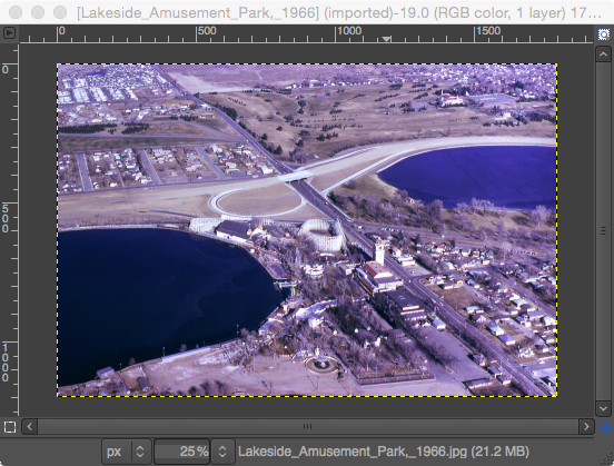
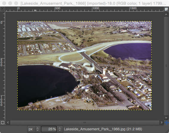
Besides graphics editing software like Photoshop and Gimp, the free and open source raw image format processing software RawTherapee (see http://rawtherapee.com/) can be used to correct color cast problems in aerial photographs due to atmospheric haze or sensor problems. An example of an image with a color cast problem is shown below. The sample can be downloaded from http://commons.wikimedia.org/wiki/File:Lakeside_Amusement_Park,_1966.jpg.
Aerial photograph courtesy of http://www.airlinesafety.com/editorials/AboutTheEditor.htm
RawTherapee has the RGB curves function that can be used to easily correct the color cast problem.

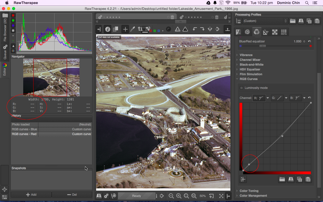
The trick to solving the color cast problem is to adjust the RGB curves to ensure the color gray values have the same RGB values.  If a gray color feature in the image e.g. an asphalt road has unequal RGB values, then the image has a color cast problem. Some times, it may be necessary to adjust the curves in the middle, dark, and/or light tones. The following example illustrates how to correct the color cast problem using RawTherapee.


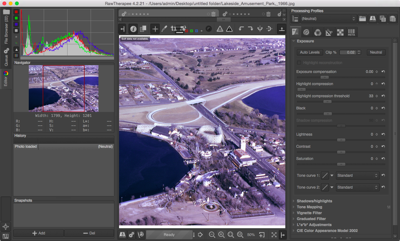
  1. Start RawTherapee. Load the image.


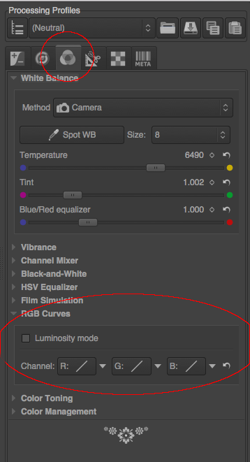
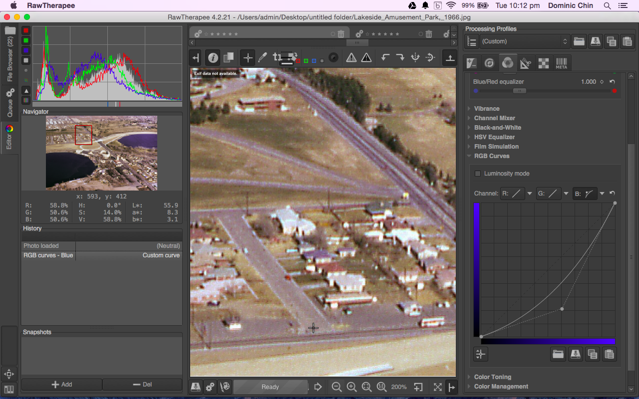
  2. Click the Color tab on the right pane. Then click RGB Curves as shown below.


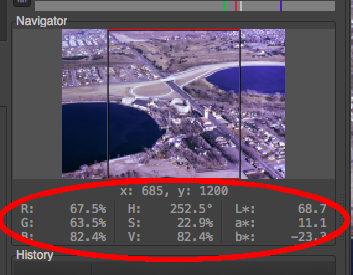
  3. Move the screen pointer around the image. Observe the RGB % values in the Navigator pane on the left when the pointer is on a mid tone gray colored feature e.g. paved road.


    Note: in this example, the RGB values are 67.5%, 63.5%, and 82.4%. The numbers indicate that there is a blue cast in the mid tone values, i.e. the blues are too high and will have to be lowered. The red and green values are alright (maybe the reds need to be lowered just a tad).
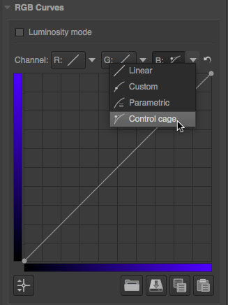
  4. In the RGB Curves, choose the Blue Channel Control Cage as shown below.


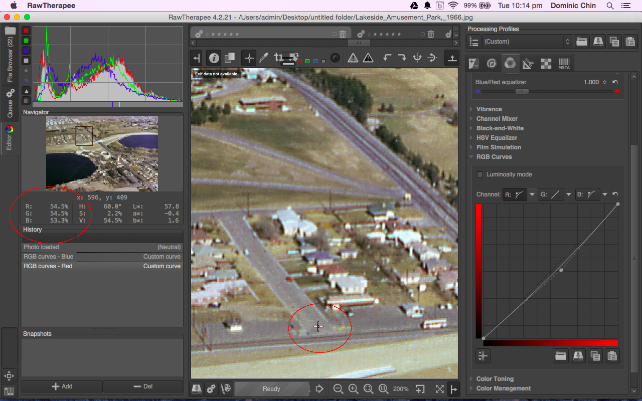
  5. Drag down the blue curve in the middle tone area. Move the cursor to the mid tone gray color feature and observe the adjusted RGB values in the Navigator pane underneath the screen pointer. Readjust the blue curve if necessary until the RGB values are about equal.


  6. I decided to adjust the mid tone red curve a little. So in the RGB Curves pane, click the Red Channel Control cage. Drag down the red curve in the mid tone area slightly and observe the adjusted RGB values in the Navigator pane. Readjust until the RGB values are about equal.


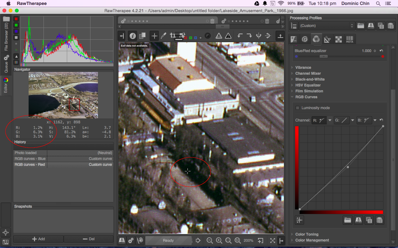
  7. No adjustment is necessary for the light tones since the color cast seems to be minimal. However the dark tones seem to need a little more red values as shown in the screenshot below.


  8. In the RGB Curves pane, drag the red curve in the dark tones slightly up. When the RGB values are about equal, the correction is complete.

    Note: after every change, always move the cursor to the dark area and check the adjusted RGB values in the Navigator pane.
  9. Now to apply the color correction, send the job to the queue and generate the image in your desired format e.g. JPEG.

    The color corrected image is created.


Monday, December 15, 2014

Create a Colored Infra Red (CIR) image from a multi-channel RGBI TIFF file using ImageMagick

Some remote sensing imagery TIFF files contain multiple bands of data such as red, green, blue, and infra-red data. In order to visualize these bands, it is necessary to combine them into an RGB format such as what is called a Colored Infra Red (CIR) display. The open source software ImageMagick can be used to generate the CIR display from the multi-channel TIFF files.

This post illustrates how to create a CIR image from an input RGBI TIFF file. In order to generate a CIR image, the input channels - RGBI has to be reordered to IRG i.e.

  • the file's output red channel is replaced with the input Infra red channel, 
  • the output green channel is replaced with the input red channel, 
  • the output's green channel is replaced with the input green channel, 
  • and the input blue channel is essentially thrown away. 


The ImageMagick command to do this is quite simple, as shown below.

$ convert input_rgbi.tif -channel rgba -separate -swap 1,2 -swap 0,1 -swap 0,3 -channel rgb -combine output_cir.tif

Note: the sequence of options is important.

  • The option -channel rgba instructs the command to read in 4 channels.
  • The option -separate splits the input channels
  • The option -swap 1,2 swaps the 2nd and 3rd channels from RGBI to RBGI
  • The option -swap 0,1 swaps the 1st and 2nd channels from RBGI to BRGI
  • The option -swap 0,3 swaps the 1st and 4th channels from BRGI to IRGB
  • The option -rgb removes the 4th channel to become IRG
  • The option -combine merges all the 3 channels back
The input RGBI file (only the RGB channels are displayed)
The CIR image generated from ImageMagick

Monday, October 21, 2013

Rotate JPEG images without loss

Sometimes due to whatever reasons, the cameras mounted on aircraft may not be aligned in the flight direction. For instance, the top of the camera may be facing the tail and not the front of the aircraft, in which case the resultant photographs will be rotated 180 degrees to the flight direction. A simple tool to perform a rotation of the JPEG photographs without the lossy compression is the Jpegtran executable available on http://jpegclub.org/jpegtran/. Using it is easy, as shown below.


  1. In a Windows Command Prompt, type in the following:

    C:> jpegtran -rotate 180 input.jpg output.jpg

    The input.jpg image is rotated by 180 degrees.

Monday, August 26, 2013

Retaining GeoTiff metadata for an image after editing in Photoshop

Sometimes for whatever reason, we have to edit a GeoTiff image in a photo manipulation software application like Photoshop. These image editing applications usually do not retain the geo-referencing information of the GeoTiff file after editing. The following screenshots show a GeoTiff image being edited in GIMP to remove some text from the image.

When the edited file is opened in a mapping software application e.g. Global Mapper, the software will be unable to detect any geo-referencing information, as shown below.


There is a way to apply back the geo-referencing information from the original GeoTiff file. As long as the edited image pixel sizes (width and height) remain the same as the original GeoTiff image, we can copy the GeoTiff metadata from the original file to the edited file using the listgeo and geotifcp executables. These programs can be downloaded as part of FWTools.

The following shows how to use the listgeo and geotifcp executables.

  1. Open up a command prompt. Type in the following:

    C:\> listgeo -no_norm original.tif > metadata.geo

    The GeoTiff file's geo-referencing metadata is copied out from the input original.tif and written to the output file metadata.geo.
  2. Next, type in the following:

    C:\> geotifcp -g metadata.geo edited.tif output.tif

    The geo-referencing info in the metadata.geo file is applied to the edited.tif file and written out to output.tif.  When the output.tif file is loaded in a mapping application, the image is placed in the correct geographic location.


Monday, July 22, 2013

Create cloud masks for aerial photos in batch

Clouds in aerial photos can interfere in the feature identification and matching stages of the ortho-photo rectification process. Depending on the software algorithm, it may be necessary to either remove the entire photo or mask out the cloud portions from the photo. If there are hundreds or thousands of photos with clouds, then it will be very tedious to manually digitize the cloud masks with a photo editing software. It would be nice to have some tool to automate the task somewhat.

Here is a simple procedure of using the free and open source software Imagemagick and the threshold option to generate the cloud masks from the photos. The assumption is that clouds in aerial photos would be brighter than the terrain underneath. An example aerial photo with clouds is shown below.
Photo credit: Kevin Payravi, Wikimedia Commons

  1. In the Windows Command Prompt, type in the following:

    C:/> convert Overview_head_of_cloud_with_shadow.jpg -threshold 40% cloud_mask.png

    Note: the threshold option tells Imagemagick to set pixel values below 40% to 0 (black) and above to white.

    The mask is created.

  2. Optional. In some software, black is the mask so it may be necessary to invert the mask with the following command.

    C:/> convert cloud_mask.png -channel rgba -transparent black -fill black -opaque white -fill white -opaque none -alpha off -define png:color-type=6 cloud_invert_mask.png

    The mask is inverted as RGB file type
Note: if there are bright objects on the ground e.g. river, stream, road, metallic rooftops, then the mask may contain these objects too. It may be necessary to edit the mask to remove these objects.

Monday, September 10, 2012

Swipe the display of raster images on and off in Global Mapper 13

Global Mapper 13 comes with a new Image Swipe Tool which as the name suggests, will swipe the display of an image on and off. As long as one or more raster layer displayed, the command can be activated. The following illustrates how the command can be used.

  1. Start Global Mapper. Load and display 2 raster layers e.g. an OpenStreetMap layer and a SRTM Worldwide Elevation Data layer.

  2. Select Tools | Image Swipe Tool.

    The Select Layer to Swipe dialog box appears.


  3. Choose the raster layer to swipe on and off. Usually this should be the uppermost layer. Click OK.

    The cursor changes to a white cross.
  4. Move the cursor to the center of the map display. Press down the left mouse button and move the cursor left or right.

    The selected raster layer display is swiped on or off at the cursor point.

Monday, June 4, 2012

Create a camera calibration chess board pattern PDF file

For calibrating a camera to calculate its intrinsic parameters e.g. focal length, principal point and distortion, some camera calibration toolboxes make use of images of chessboard patterns taken with the camera. One such toolbox is this open-source software from this site http://graphics.cs.msu.ru/en. To create this calibration chess board pattern, there are a variety of methods that can be employed to generate it.


In this post, I shall use the free and open-source vector illustration software Inkscape to create an A4 sized 8x3cm by 6x3cm tiles calibration pattern. Inkscape can be downloaded from this site http://inkscape.org.

  1. Start Inkscape.

  2. Select File | Document Properties.

    The Document Properties dialog box appears.
  3. In the Page Size list box, select A4. In the Default Units field, choose cm. Close the Document Properties dialog box.
  4. In the toolbox, click the Create rectangles and squares icon.
  5. Click and drag out a rectangle on the page.

  6. In the Change W and H fields, type in 3.
  7. In the toolbox, click the Select and transform objects icon.

  8. Select Edit | Copy.
  9. Select Edit | Paste. Repeat to paste the square two more times.

  10. Change the fill color of two squares to black. Change the fill color of two squares to white.

  11. Click the Select and transform objects icon and select all squares.
  12. Select Object | Rows and Columns.

    The Rows and Columns pane appears.
  13. Ensure the Rows and Columns are set to 2. Ensure the Set spacing is 0. Click Arrange.

    The squares are rearranged.
  14. Ensure all the squares are selected. Select Object | Group.

    All the squares are grouped as a single object.
  15. Select Edit | Copy.
  16. Select Edit | Paste. Repeat 10 more times to place a total of 48 (3x4x4) tiles.
  17. Press CTRL-A.

    All the tiles are selected.
  18. Select Object | Rows and Columns if the Rows and Columns pane is not displayed.

    The Rows and Columns pane is displayed.
  19. In the Rows field, type in 4. In the Columns field, type in 3. Click Arrange.

    The calibration chess board pattern is complete.
  20. Select File | Save As.

    The Select file to save to dialog box appears.
  21. In the Save as type field, choose Portable Document Format (*.pdf). Browse and type in a file name e.g. calib.pdf. Click Save.

    The file is saved.

Monday, May 14, 2012

Re-align a raster image to the corners in Gimp

The free and open source software Gimp is an Adobe Photoshop like software that can be used to edit or adjust raster images. If you use the Gimp software for editing raster images for contrast, brightness, color balance, etc. then it just might be possible to make a mistake and shift the entire raster image layer so that it is no longer align to the canvas corners. The screenshot below shows a shaded relief raster image that has been mistakenly shifted - the bottom right is no longer aligned to the corner.

In order to shift the raster layer back precisely, the Gimp ruler guide lines can be used as described below.

  1. In the Gimp Toolbox, click the Zoom tool and zoom closer to the corner.


  2. On the top horizontal ruler bar, press down the left mouse button and drag out a horizontal guide line until it snaps to the bottom of the canvas.


  3. On  the left vertical ruler bar, press down the left mouse button and drag out a vertical guide line until it snaps to the right of the canvas.
  4. In the Toolbox, click the Move tool. Press down the left mouse button on the raster image and drag the image so that the bottom right corner snaps  to the horizontal and vertical guide lines.

    The raster image is snapped to the canvas corner.


    The raster image is now correctly aligned again.