Tuesday, September 30, 2008

Accessing DXF Files in GeoMedia

Before you can display any DXF layers or features in GeoMedia, you have to create and define a CAD Server Schema file. This schema file simply defines a collection of DXF files within the DXF warehouse, and all the DXF layers/features within the DXF files. You must classify the DXF graphics as GIS features/layers based on some unique classification criteria such as the DXF EntityColor, LayerName etc. For instance, you may have created AutoCAD polygons representing land use boundaries on a layer named as 'LANDUSE'. If so, you can define a classification criteria that states that all entities on the DXF layer 'LANDUSE' are LandUse features.

Here are the steps to create the schema file and to connect to the DXF warehouse.

Defining the CAD Server Schema File
  1. On the Windows desktop, select Start > All Programs > GeoMedia > Utilities > Define CAD Server Schema File.

    The Define CAD Server Schema File dialog box appears.


  2. In the Define CAD Server Schema File dialog box, select File > New.

    The New dialog box appears.


  3. Choose AutoCadTemplate.csd and click New.

    The Select Map Files dialog box appears.


  4. In the Select Map Files dialog box, click New.

    The Browse For Folder dialog box appears.

  5. Browse and choose the folder containing your DXF file(s), e.g. D:\Warehouses\dxf\. Click OK.

    The Select Map Files dialog box displays the selected folder and any DXF files contained in the folder.


  6. In the Map files list box, toggle on the DXF file(s). Click OK when done.

    The Select Coordinate System Files dialog box appears.


  7. In the Coordinate system files list box, toggle on the coordinate system file suitable for the DXF data. Click OK.

    Note: Prior to this step, you must have created and defined a suitable coordinate system file using the GeoMedia Define Coordinate System File utility.

    The Define Feature Class dialog box appears.


  8. In the Define Feature Class dialog box, click New.

    The New dialog box appears.

  9. In the Name field, type in a suitable name for a feature in the DXF data, e.g. LandParcel.
  10. In the Geometry type list box, toggle on an appropriate geometry type for the feature, e.g. AreaGeometry.

    The New dialog box may look like this.


  11. Click the Graphic Attributes tab.
  12. Toggle on any Graphic Attribute Name you wish to expose as attributes in GeoMedia, e.g. EntityColor, BlockName, EntityType, etc.


  13. Click the Criteria tab.
  14. Toggle on the DXF Attribute Name(s) that defines the current feature and type in the Classification Criteria.

    For example, if you have polygons representing land parcels in the DXF file and they are stored uniquely on a DXF layer named as 'LAND_PARCELS', then you would toggle on the LayerName attribute and typed in LAND_PARCELS in the Classification Criteria field.


  15. Click OK.

    The Define Feature Class displays the newly defined DXF feature.


  16. If you have additional features to define, repeat the previous steps 8 to 15.
  17. In the Define Feature Class dialog box, click Close.
  18. In the Define CAD Server Schema File dialog box, select File > Save.

    The Save As dialog box appears.


  19. In the File name field, type in a name for the new CAD Schema definition file, e.g. Dxf.csd.
  20. Click Save.
  21. Close the Define CAD Server Schema File dialog box.
Connecting to a CAD(DXF) Warehouse
You can now connect to the DXF file via the CAD Server Schema in GeoMedia.
  1. In GeoMedia, select Warehouse > New Connection.

    The New Connection dialog box appears.


  2. In the Connection type list box, select CAD.
  3. In the Connection name field, type in an appropriate name, e.g. DXFConnection.
  4. In the CAD Server Schema file field, click Browse and select the schema file you created earlier.
  5. Click OK.

    GeoMedia is now connected to the DXF data warehouse.
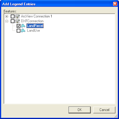
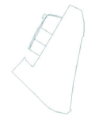
Once connected, you can display the DXF data, by selecting Legend > Add Legend Entries and choosing the DXF feature(s) as shown below.


Monday, September 29, 2008

Batch load a Coordinate System File to a GeoMedia GeoWorkspace document

GeoMedia's GeoWorkspace file is a document used by GeoMedia to store user preferences, legends, warehouse connections, settings, and other objects. The GeoWorkspace document has a default coordinate system assigned to it. You can change the workspace's active coordinate system interactively by using the GeoMedia application's GeoWorkspace Coordinate System dialog box (shown below) - the dialog box can be opened by selecting View > GeoWorkspace Coordinate System.

However, if you have a large number of existing GeoWorkspace documents for which you want to change the coordinate system, then doing it through the GeoMedia application's graphical user interface will be very tedious as you need to do it one by one.

So I developed a .NET console application to do the same thing but in batch mode. You simply need to create a GeoMedia coordinate system file (.csf) of your new coordinate system. Then pass in the name of the coordinate system file and the GeoWorkspace file to the console application. Example usage is shown below.


C:\> batchloadcsf -h
Batch load a coordinate system file to a GeoWorkspace file.

BATCHLOADCSF [-CSF coordinate system file] [-GWS geoworkspace file]

-CSF Specifies a coordinate system file to load.

-GWS Specifies the GeoMedia GeoWorkspace file for setting the coordinate system.


C:\> batchLoadCSF -csf CassiniSoldner.csf -gws batch1.gws
Loading csf 'C:\Temp\test\CassiniSoldner.csf' to 'C:\Temp\test\batch1.gws'
Completed


You can create a DOS batch file and loop through all your GeoWorkspace files. At the end of it, all your GeoWorkspace files will be loaded with the coordinate system from the coordinate system file.

Tuesday, September 23, 2008

Create Labels from Point Geometries with Functional Attributes

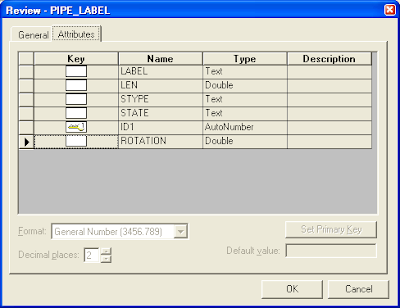
Unlike CAD formats like DGN or DWG, some GIS formats like Shape File do not have a geometry type for text labels. The closest are point geometries with attached database attributes for storing the text label string, angle of rotation, size, etc. See the screenshot below of an example.


As these are point geometries, they are displayed as point geometries (no surprise) in GeoMedia. But, there is a way to make use of the associated text attributes and point geometries to create text label features in GeoMedia. The tool to use is the Functional Attributes.

Here are the steps to create the text labels in GeoMedia.
  1. Select Analysis > Functional Attributes.

    The Functional Attributes dialog box appears.

  2. In the Add functional attributes for combo box, select the point feature, e.g. PIPE_LABEL.

    The Functional Attributes dialog box may look like this.


  3. Click New.

    The Functional Attribute dialog box appears.

  4. In the Functional attribute name field, type in a meaningful name, e.g. TextLabel.
  5. In the Categories list box, click Geometry.
  6. In the Functions list box, click CreateTextPoint.

    The description of the CreateTextPoint function appears below.
    CREATETEXTPOINT(Geometry, Text, Alignment, Orientation)
    Creates a text point geometry from the given parameters.

  7. In the Expression field, type in the following. Note: Replace Geometry with the name of your data's geometry field; replace LABEL with the name of your data's text label field' replace ROTATION with the name of your data's angle of rotation field.

    CREATETEXTPOINT(Input.Geometry, Input.LABEL, 0, Input.ROTATION)

    The Functional Attribute dialog box may look like this.


  8. Click OK and Close.

    The Functional Attribute dialog box is closed.

  9. In the Query name field, type in a meaningful name, e.g. TEXT_PIPE_LABEL.
  10. Toggle off Display functional attributes in data window.

    The Functional Attributes dialog box may look like this.


  11. Click OK.

    The text label feature is created and displayed in the map window.

Monday, September 22, 2008

Export GeoMedia Layout Window to PDF Example Code

There is a great open source C# library that you can use to build GeoMedia custom programs to create PDF files. It is called iText# or iTextSharp - a port of the iText open source java library written entirely in C# for the .NET platform. It can be downloaded here.

I have combined this library with GeoMedia's RenderToRasterFileService to export out the Layout Window's active sheet contents as PDF files. Below is a simple example that locates the Layout Window and exports its active sheet to an A0 sized, landscape PDF file via an intermediate PNG raster file. This example will work with a running instance of GeoMedia, which has data loaded in the Layout Window.


GeoMedia.LayoutWindow layoutWnd = null;
RenderToRasterFile.RenderToRasterFileService renderer = null;
GMLayout.Application layoutVw = null;
GMLayout.Sheet sheet = null;

//Get the GeoMedia framework's windows collection
GeoMedia.Windows wnds = (GeoMedia.Windows)this._application.Windows;

//Loop through all the GeoMedia windows to find the layout window
for (int i = 1; i <= wnds.Count; i++)
{
if (wnds.Item(i) is GeoMedia.LayoutWindow)
{
layoutWnd = (GeoMedia.LayoutWindow)wnds.Item(i);
break;
}
}

if (layoutWnd == null)
throw new Exception("Unable to find the Layout Window");

//Get the layout window's active sheet
layoutVw = (GMLayout.Application) layoutWnd.LayoutView;
sheet = layoutVw.ActiveSheet;

//Create the RenderToRasterFile service and set the output raster file properties
renderer = (RenderToRasterFile.RenderToRasterFileService) this._application.CreateService("GeoMedia.RenderToRasterFileService");
renderer.InputDisplay = sheet;
renderer.OutputFileName = @"C:\temp\test.png";
renderer.OutputFileResolution = 300;
renderer.OutputFileType = RenderToRasterFile.FileFormatConstants.gmRenderToRasterFilePNG;

//Render the sheet into a PNG file
renderer.Execute();

if (File.Exists(@"C:\temp\test.png") == false)
throw new Exception("Test.png not created successfully");

iTextSharp.text.Document doc = null;
iTextSharp.text.Image img = null;
iTextSharp.text.Rectangle pageRect = null;

//Define a PDF page as A0 size with landscape orientation
pageRect = PageSize.A0.Rotate();

//Create a new PDF document with A0 sized, landscape pages
doc = new iTextSharp.text.Document(pageRect);
PdfWriter.GetInstance(doc, new FileStream(@"C:\temp\test.pdf", FileMode.Create));
doc.Open();

//Read the PNG raster file
img = Image.GetInstance(@"C:\temp\test.png");

//Adjust the PNG raster file to fit the PDF page
img.Alignment = Image.ALIGN_CENTER;
img.SetAbsolutePosition(0, 0);
img.ScaleToFit(pageRect.Width, pageRect.Height);

//Add the PNG file to the PDF document
doc.Add(img);
doc.Close();

Monday, September 15, 2008

Programming GeoMedia: CreateService Method

If you are developing a driving GeoMedia custom application using .NET, you may find that some values returned by a GeoMedia object or service may appear odd or incorrect. For example, in the C# code listing below I am trying to use the GeoMathService to calculate a geometry range.

GeoMath.GeoMathService gmathSvc;
GeoMath.point lowerLeftPoint, upperRightPoint;

lowerLeftPoint = new GeoMath.pointClass();
upperRightPoint = new GeoMath.pointClass();

gmathSvc = (GeoMath.GeoMathService) this._application.CreateService("GeoMedia.GeoMathService");
gmathSvc.GetRange(objGeom, lowerLeftPoint, upperRightPoint);

Using the Visual Studio debugger to view the values of lowerLeftPoint.X and lowerLeftPoint.Y, I get the following:

X = 28671.723701195806
Y = 8.6309974485990875E+182

The Y value is overly large and incorrect.

As values are being passed across process boundaries - from managed .NET application code to GeoMedia's COM object and back, memory management problems could arise. The way to avoid the cross process memory allocation problems is to use the GeoMedia application to allocate and manipulate the memory with its CreateService method instead of C#'s new operator.

The good C# code listing is shown below:

GeoMath.GeoMathService gmathSvc;
GeoMath.point lowerLeftPoint, upperRightPoint;

lowerLeftPoint = (GeoMath.point) this._application.CreateService("GeoMedia.point");
upperRightPoint = (GeoMath.point) this._application.CreateService("GeoMedia.point");

gmathSvc = (GeoMath.GeoMathService) this._application.CreateService("GeoMedia.GeoMathService");
gmathSvc.GetRange(objGeom, lowerLeftPoint, upperRightPoint);

Running in debug mode, the values of lowerLeftPoint can be viewed as the following:
X = 28671.723701195806
Y = 28628.034157585753

The values look reasonable.

Thursday, September 11, 2008

Kill GeoMedia Process in GeoMedia .NET Application

While developing custom driving GeoMedia custom applications in .NET, I notice that even though references to GeoMedia COM objects - connections, GRecordsets, etc have been explicitly released at the end of the program, the GeoMedia process started by my application remains running in the background. It seems this is dependent on the GeoMedia objects and methods I used - sometimes the GeoMedia process terminate gracefully, sometimes not (especially if I use the GMLayout SmartFrames2D' CreateEmbed method).

I decided to put in explicit handling to kill the GeoMedia process in my class' constructor and destructor. The basic idea is to get the process id of my custom application's GeoMedia instance in the constructor. Then when exiting the custom application in the class' destructor, I use the process id to kill off the GeoMedia process.

The C# code listing below illustrates the basic idea.


using System;
using System.Collections;
using System.Diagnostics;
using GeoMedia = Intergraph.GeoMedia.GeoMedia;

class GeoMediaWrapper
{
private int _myProcessId; //my GeoMedia process id
private GeoMedia.Application _application;
public GeoMediaWrapper()
{
Type GeoMediaType;

//Build an array list of all running GeoMedia
//processes first

ArrayList processList = new ArrayList();
foreach (Process proc in Process.GetProcessesByName("GeoMedia"))
processList.Add(proc.Id);

//Start up an instance of GeoMedia
GeoMediaType = Type.GetTypeFromProgID("GeoMedia.Application", "localhost", true);
this._application = (GeoMedia.Application)Activator.CreateInstance(GeoMediaType);

//Loop through all the running GeoMedia processes.
//If the id does not exist in the previously built list,
//then this must be my
GeoMedia process id number.

foreach (Process proc in Process.GetProcessesByName("GeoMedia"))
if (!GMProcs.Contains(proc.Id))
{
//this is my GeoMedia process!
this._GMProcId = proc.Id;
}
}
~GeoMediaWrapper()
{
//Kill off my GeoMedia process
Process.GetProcessById(this._GMProcId).Kill();
}
//...etc...
}

Tuesday, September 9, 2008

Release References to GeoMedia COM Objects in C#


When developing Driving GeoMedia custom applications using .NET, if you don't free up the references to GeoMedia objects, you will encounter the above error message when exiting your custom application. As GeoMedia objects are built as Windows COM (Common Object Model) objects, the .NET framework garbage handling facility will not automatically close and free up all the references to the GeoMedia objects. You will have to do an explicit COM object release using the .NET System.Runtime.InteropServices.Marshal class' FinalReleaseComObject method.

For example in your GeoMedia Wraper class' destructor you could code the following:

using System.Runtime.InteropServices;
using GeoMedia = Intergraph.GeoMedia.GeoMedia;

class GeoMediaWrapper
{
private GeoMedia.Application _application = null;
public GeoMediaWrapper()
{
Type GeoMediaType = Type.GetTypeFromProgID("GeoMedia.Application", "localhost", true);
this._application = (GeoMedia.Application) Activator.CreateInstance(GeoMediaType);
}
~GeoMediaWrapper()
{
if (this._application != null)
Marshal.FinalReleaseComObject (this._application);
}
//.... etc ...
}

Friday, September 5, 2008

Accessing Shape Files in GeoMedia

Figuring out how to display DGN, DWG, DXF or SHP files in GeoMedia for beginners without formal training can be difficult sometimes. In GeoMedia terminology, those external files are called as warehouses; and to display the data residing in those warehouses, you have to make a connection to it first. Once you are connected, you can then display and manipulate the data in a map window as legend entries. That's essentially it. Now, how do you get connected to a shape file warehouse? First, you have to create a warehouse configuration file first. Here are the detailed steps:

Define Warehouse Configuration File
  1. On the Windows desktop, select Start | All Programs | GeoMedia | Utilities | Define Warehouse Configuration File.

    The Define Warehouse Configuration File dialog box appears.

  2. In the Data server combo box, choose ArcView.
  3. In the Warehouse information group, click Browse and select the ArcView workspace folder where you have stored your shape files, e.g. C:\Warehouses\ShapeFiles\.
  4. If you have an existing Coordinate System file, click Browse and select your existing coordinate system file, e.g. C:\Warehouses\ShapeFiles\TransverseMercator.csf.

    If you do not have a coordinate system file, click Coordinate System File and define a new coordinate system file appropriate for your shape files in the Coordinate System Properties dialog box as shown below.


    The Define Warehouse Configuration File dialog box may look like the screen below.


  5. In the Define Warehouse Configuration File dialog box, click Next.

    The Define Warehouse Configuration File keywords are displayed.


  6. Click Finish.

    The warehouse configuration file is created.
Once you have a proper warehouse configuration file created for your shape files, you only need to make a connection to the shape files warehouse the next time. Here are the steps to make a connection in GeoMedia.

Connecting to a Shape Files Warehouse
  1. In GeoMedia, select Warehouse | New Connection.

    The New Connection dialog box appears.

  2. In the Connection type list, select ArcView.
  3. In the Connection name field, type in a suitable connection name, e.g. ArcView Connection 1.
  4. In the Connection description fields, type in a suitable description (this is optional), e.g. My Shape Files Connection.
  5. In the ArcView workspace folder fields, click Browse and select the folder containing the shape files, e.g. C:\Warehouses\ShapeFiles\.

    The New Connection dialog box may look like the screen below.


  6. Click OK.

    GeoMedia is now connected to the shape files warehouse.

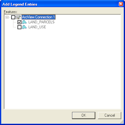
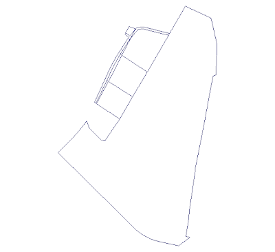
Once you are connected to the warehouse, you can then display the Shape files in GeoMedia. For example, you can select Legend | Add Legend Entries and choose the features you want to display as shown below.

Wednesday, September 3, 2008

The New Google Chrome Browser

Google has just released a beta version (0.2.149.27) of its new browser called Chrome. I downloaded it and took it out for a spin. I like the feel of the browser - it seems quite responsive and fast - pages are loaded quickly. I also like the integrated address / search entry field - I don't need to go to a separate search field to type in my search query. I don't like the page rendering errors - Chrome refused to display the Yahoo web site as shown in the screen shot below.


I also noticed that images are not rendered properly according to the style definitions, as shown in the Singapore Palm Users Group web site below. The text don't flow correctly around the images.

The Chrome browser also broke my Google Maps web sites - see the screen shot below.

From my brief spin around the block, I'm going to hold off Chrome until Google improves the browser.

Useful Namespaces for GeoMedia Programming in .NET

using GeoMedia = Intergraph.GeoMedia.GeoMedia;
using GMLayout = Intergraph.GeoMedia.GMLayout;
using PCSS = Intergraph.GeoMedia.PCSS;
using GMService = Intergraph.GeoMedia.GMService;
using PService = Intergraph.GeoMedia.PService;
using PBasic = Intergraph.GeoMedia.PBasic;
using GDO = Intergraph.GeoMedia.GDO;
using PClient = Intergraph.GeoMedia.PClient;
using PDBPipe = Intergraph.GeoMedia.PDBPipe;
using GeoMath = Intergraph.GeoMedia.GeoMathSvc;
using PView = Intergraph.GeoMedia.PView;
using MapviewLib = Intergraph.GeoMedia.MapviewLib;

The above C# code snippet shows a list of useful namespaces to include when developing GeoMedia custom applications or commands. Use the namespace GeoMedia (Intergraph.GeoMedia.GeoMedia) to access the methods and properties of the GeoMedia application framework such as the GeoWorkspace document. If you plan to do a lot of layout window programming, then the GMLayout namespace is definitely a must. Include the GDO namespace to access the Geographic Data Objects methods and properties especially if you intend to read recordsets and databases in your code; in addition, the PBasic, PDBPipe namespaces would be very useful in writing code that works with geometries. Lastly, use the PView and MapviewLib namespaces if your code is used for displaying features in the Map Windows.