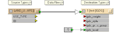
Most times, users will want to control and define the output levels of the output DGN graphic elements since levels is a useful way to organize the graphical data e.g. level 1 for vegetation land use, level 2 for park land use, etc.
In this posting, I describe a way using FME mapping file to define and control the destination level. I am assuming that I have an attribute in the source feature that stores the level number.
- Use the FME Universal Translator to generate a mapping file from your source format e.g. ESRI Shape to the destination MicroStation Design format.

- Use a text editor to open up the resultant mapping file e.g. mapping.fme.
The mapping file may look like this.
# ============================================================================
# Source feature type definition section
# ============================================================================
SHAPE_DEF LAND_USE \
SHAPE_GEOMETRY shape_polygon \
USE_TYPE char(50) \
IGDS_LEVEL number(10,0) \
ID number(10,0)
# ============================================================================
# Transformation section
# ============================================================================
SHAPE LAND_USE \
USE_TYPE %USE_TYPE \
ID %ID
IGDS 1 \
igds_type igds_solid \
USE_TYPE %USE_TYPE \
ID %ID - In the Transformation section for the source format, add in the following line in bold.
SHAPE LAND_USE \
USE_TYPE %USE_TYPE \
IGDS_LEVEL %IGDS_LEVEL \
ID %ID - In the Transformation section for the destination IGDS format, replace the number "1" with the text "level" and add in the following line in bold.
Note: igds_level must be in lower case.
IGDS level \
igds_type igds_solid \
USE_TYPE %USE_TYPE \
igds_level %IGDS_LEVEL \
ID %ID - Save the changes and close the mapping file. Now when you run the translation, the DGN graphic elements will be created in the level defined in the IGDS_LEVEL attribute of the source feature.

No comments:
Post a Comment