Monday, February 26, 2018

Use PDAL to register a point cloud to control points

Sometimes, some 3D LiDAR point cloud data are not at the correct location or they are not aligned with other point clouds. When this happens, at least 3 control points from the point cloud and the reference need to be identified and a transformation matrix (usually a 4x4 homogeneous matrix) be calculated.

Once the matrix has been calculated, PDAL's transformation filter can then be used to perform the registration or transformation of the point cloud to the reference.

While PDAL can apply the transformation, it does not have a tool for calculating the matrix. This has to be done externally. This post uses a simple WebApp calculator at this site https://dominoc925-pages.appspot.com/webapp/calc_transf3d/default.html to calculate a rigid 4x4 transformation matrix given 2 corresponding sets of 3 or more control points.

Identifying 2 sets of corresponding control points

  1. Using a point cloud viewer such as FugroViewer, identify 3 or more source control points from the unregistered point cloud., e.g. p1, p2, p3 and p4.


  2. Using a GPS receiver or from a database, identify the corresponding points from the destination reference system.


Calculating the 4x4 transformation matrix
  1. Open up url https://dominoc925-pages.appspot.com/webapp/calc_transf3d/default.html in an Internet browser.
  2. In the Source 3D points field, type or paste in the source control point coordinates from the previous section.


  3. In the Destination 3D points field, type or paste in the corresponding control points from the destination reference system from the previous section.
  4. Click Calculate.

    The 4x4 transformation matrix and root mean square error is calculated.


    Note: if the RMSE is large, then there may be some error in the input coordinates.
  5. Using a text editor, create a PDAL pipeline JSON file which specifies the input, filter, and output. Copy and paste the 4x4 transformation matrix into the matrix field in the JSON file as shown below. Replace the commas with blanks. 
{
  "pipeline":[
    "input.laz",
    {
      "type":"filters.transformation",
      "matrix":"
0.21095277662308629 0.9774781497556848 -0.00594918357528593 23238.318780198064 
-0.9774332258657229 0.21100438075203337 0.01007175640974158 30100.055196603218 
0.011100225616467532 0.0036902647131527543 0.9999315811282344 32.53070599039722 
0 0 0 1"
    },
    {
      "type":"writers.las",
   "compression": "laszip",
      "filename":"output.laz"
    }
  ]
}

Running the transformation

  1. In Windows, open up the OSGeo4W command prompt.

    The Administrator: OSGeo4W Shell appears.


  2. In the Command Prompt, type in the following and press RETURN:

    C:> pdal pipeline transform_pipeline.json

    where transform_pipeline.json is the JSON file created in the previous section.

    The point cloud is transformed.

Monday, February 19, 2018

WebApp for calculating the 4x4 transformation matrix between 2 corresponding sets of 3D points

In working with 3D point clouds, one of the task may be to register or transform the point cloud to known ground control points (GCPs) on the ground with corresponding control points in the point cloud. For instance, the screen shot below shows the point cloud with four control points p1, p2, p3, and p4.

Note: At least 3 corresponding set of points are needed to calculate a rigid transformation matrix.

From the point cloud, the from-control points can be measured:

On the ground, the actual ground control points can be obtained, perhaps from a GPS receiver:


With the measured points from the point cloud and the corresponding control points on the ground, a 4x4 homogeneous transformation matrix can be calculated and used to rigidly transform the point cloud to the actual ground coordinate system. 

This WebApp calculator at https://dominoc925-pages.appspot.com/webapp/calc_transf3d/default.html can be used to calculate the 4x4 transformation matrix, as well as the root mean square error (RMSE) as an indicator of the quality of the control points i.e. the smaller the RMSE, the better they are. The WebApp uses the Numeric Javascript matrix library from http://www.numericjs.com/ for performing the required SVD decomposition to calculate the transformation matrix. Note that the library has some unfixed bugs in the SVD decomposition for certain cases and I may probably replace this with an alternative solution in future.  
  1. Paste the "from control points" into the Source Points text area field. 

  2. Paste the ground control point values into the Destination Points text area field.
  3. Click the Calculate button.


    The resultant transformation matrix appears in the 4x4 Transformation Matrix field. The RMSE for the calculation is displayed in the RMSE field.

Monday, February 12, 2018

Displaying WKT geometry string in QGIS with getWKT plugin

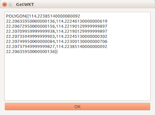
If you want to display the Well Known Text (WKT) string of a selected geometry in QGIS, there is a plug-in getWKT that can be used for this purpose. The screen shot below shows the Plug-in Manager's description of the getWKT plug-in.
 
 To use the getWKT plug-in, do the following:
  1. In QGIS, click the Select Features by area of single click button. Using the mouse, click on a feature.

    A feature is selected and highlighted in yellow.
  2. Then click the getWKT icon in the tool bar.


    The GetWKT dialog box appears with the WKT string of the selected geometry.

Monday, February 5, 2018

Find the 3x3 transformation matrix given a set of 3D points using Octave

I have 2 corresponding pair of 3 measured 3D points - one original coordinates (let's call as X) and the other destination or reference coordinates (say Y) . I wanted to find the transformation matrix (say A) that can transform the original coordinates to the destination coordinates.

Octave (an open source software alternative to Matlab. See https://www.gnu.org/software/octave/) has the tools to determine the 3x3 transformation matrix. This post shows how to perform the calculation.

Given the 3 original measured 3D points X:
x1 = (2, -1, 2)
x2 = (-1, 2, 2)
x3 = (2, 2, -1)

And the 3 measured destination 3D points Y:
y1 = (-2, -9, -30)
y2 = (-23, 12, 9)
y3 = (13, 6, -6)

  1. First, write out the transformation and coordinates in the following form

    AX=Y

    where A is the unknown transformation matrix,
    X is a matrix of the original coordinates formed by concatenating the points as column vectors X = [x1, x2, x3]
    Y is a matrix of the destination coordinates formed by concatenating the points as column vectors Y = [y1, y2, y3]
  2. Run Octave. In the command prompt, enter the X matrix values:

    $> X = [2 -1 2; -1 2 2; 2 2 -1]
  3. In the prompt, enter the Y matrix values:

    $> Y = [-2 -23 13; -9 12 6; -30 9 -6]
  4. Now calculate the inverse of X by typing the following into the prompt.

    $> IX = inv(X)
  5. The transformation matrix A can be calculated by simply multiplying the matrix Y with the inverse of X. Type in the following at the prompt:

    $> A = Y * IX
  6. Optional. Use the calculated matrix A and multiply with the original coordinates X and check whether the resultant values matches the measured Y coordinates.