Monday, March 4, 2013

How to build 64-bit versions of libgeotiff for Windows

I could not find 64-bit binaries of the open-source libGeotiff library so I decided to download the most recent source code from http://trac.osgeo.org/geotiff/ so that I could use Microsoft Visual Studio 2010 to compile make my own. Other libraries are also required so I downloaded the latest source code for libTiff from http://download.osgeo.org/libtiff/ and Proj4 from http://trac.osgeo.org/proj/. I have no problems compiling libTiff and Proj4 as is but I had to modify the libGeotiff's makefile.vc file to make it compile successfully. Note that successful compilation does not necessarily mean the 64 bit executables will run successfully.


Compile 64 bit version of Proj4
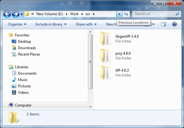
  1. Extract the Proj4 source code into a folder e.g. C:\Work\src\proj-4.8.0\
  2. Select Start | All Programs | Microsoft Visual Studio 2010 | Visual Studio Tools | Visual Studio x64 Win64 Command Prompt.

    The Win64 Command Prompt appears.
  3. In the Command Prompt, type in and enter the following:

    C:\> cd \Work\src\proj-4.8.0
  4. Run the nmake build command in the Command Prompt:

    C:\> nmake /f makefile.vc

    The 64 bit version of Proj4 is created.
Compile 64 bit version of libTiff
  1. Extract the libTiff source code into a folder e.g. C:\Work\src\tiff-4.0.3\.
  2. Open up the Win64 Command Prompt if it is not  already on the screen.
  3. In the Command Prompt, type in the following command.

    C:\> cd \Work\src\tiff-4.0.3\
  4. Run the nmake build command in the Command Prompt.

    C:\> nmake /f makefile.vc

    The 64 bit version of libTiff is created.
Compile 64-bit version of libGeotiff
  1. Extract the libGeotiff source code into a folder e.g. C:\Work\src\libgeotiff-1.4.0\.
  2. Use a text editor to open up the header file geo_config.h. Add in the line #define BUILD_AS_DLL 1 as shown in red below.

    /* geo_config.h.  Generated from geo_config.h.in by configure.  */
    #ifndef GEO_CONFIG_H
    #define GEO_CONFIG_H
    
    #define BUILD_AS_DLL 1
    
    /* Define if you have the ANSI C header files.  */
    #define STDC_HEADERS 1
    
    /* Define if you have the <stdlib.h> header file.  */
    #define HAVE_STDLIB_H 1
    
    /* Define if you have the <string.h> header file.  */
    #define HAVE_STRING_H 1
    
    /* Define if you have the <strings.h> header file.  */
    #define HAVE_STRINGS_H 1
    
    #define HAVE_LIBPROJ 1
    /* #undef HAVE_PROJECTS_H */
    
    #endif /* ndef GEO_CONFIG_H */
    

  3. Use a text editor to open up the libGeotiff's makefile.vc file.
  4. Replace the contents of makefile.vc with the contents below.

    Note: the parts that were modified are colored in red.

    #
    # Typically the only thing that needs to be changed are the paths to the
    # TIFF tree.  Note that we expect an existing build tree, in part because we
    # need private include files from libtiff, but also we need access to getopt.h.
    # in the ports directory.
    #
    # You may want to add optimization options to the CFLAGS macro as well. 
    #
    
    TIFF = C:\Work\src\tiff-4.0.3
    PROJ4 = C:\Work\proj-4.8.0
    
    TIFF_INC = -I$(TIFF)\libtiff
    TIFF_LIB = $(TIFF)\libtiff\libtiff.lib
    TIFF_LIB_DLL = $(TIFF)\libtiff\libtiff_i.lib
    PROJ4_INC = -I$(PROJ4)\src
    PROJ_LIB = $(PROJ4)\src\proj.lib
    PROJ4_LIB_DLL = $(PROJ4)\src\proj_i.lib
    
    # Installation locations (with install, or devinstall targets)
    PREFIX =    release    
    BINDIR =    $(PREFIX)\bin
    LIBDIR =    $(PREFIX)\lib
    INCDIR =    $(PREFIX)\include
    DATADIR =    $(PREFIX)\share\epsg_csv
    
    #
    CC      = cl
    INCL    = -I. -Ilibxtiff $(TIFF_INC) $(PROJ4_INC)
    
    
    # Pick the first LIBS definition for a static libtiff.lib or the second
    # to link against the libtiff DLL.
    
    #LIBS    = geotiff.lib $(TIFF_LIB) $(PROJ4_LIB)
    LIBS    = geotiff_i.lib $(TIFF_LIB_DLL) $(PROJ4_LIB_DLL)
    
    DLLNAME = geotiff.dll
    
    # Set optimization or debug flags here.
    CFLAGS  = $(INCL) /MD /Ox /nologo
    #CFLAGS  = $(INCL) /MD /Zi /nologo
    
    #
    OBJS    = \
        xtiff.obj \
        geo_free.obj \
        geo_get.obj \
        geo_names.obj \
        geo_new.obj \
        geo_print.obj \
        geo_set.obj \
        geo_tiffp.obj \
        geo_write.obj \
        geo_extra.obj \
        geo_trans.obj \
        geo_normalize.obj \
        geotiff_proj4.obj \
        geo_simpletags.obj \
        cpl_csv.obj \
        cpl_serv.obj
    
    all:    geo_config.h geotiff.lib $(DLLNAME) listgeo.exe geotifcp.exe
    
    listgeo.exe:    bin\listgeo.c geotiff.lib
        $(CC) $(CFLAGS) bin\listgeo.c $(LIBS)
        
    geotifcp.exe:    bin\geotifcp.c geotiff.lib
        $(CC) $(CFLAGS) bin\geotifcp.c bin\getopt.c $(LIBS)
        
    gt_update.exe:    bin\gt_update.c geotiff.lib
        $(CC) $(CFLAGS) bin\gt_update.c bin\getopt.c geotiff.lib $(LIBS)
        
    geotiff.lib:    $(OBJS)
        lib /out:geotiff.lib $(OBJS)
    
    #
    $(DLLNAME):    $(OBJS)
        link /dll /out:$(DLLNAME) /implib:geotiff_i.lib $(OBJS) $(TIFF_LIB_DLL) $(PROJ4_LIB_DLL)
        if exist $(DLLNAME).manifest mt -manifest $(DLLNAME).manifest -outputresource:$(DLLNAME);2
    
    geo_config.h:    geo_config.h.vc
        copy geo_config.h.vc geo_config.h
    
    xtiff.obj: libxtiff\xtiff.c
        $(CC) -c $(CFLAGS) libxtiff\xtiff.c
    
    geo_free.obj: geo_free.c
        $(CC) -c $(CFLAGS) geo_free.c
    
    geo_get.obj: geo_get.c
        $(CC) -c $(CFLAGS) geo_get.c
    
    geo_names.obj: geo_names.c
        $(CC) -c $(CFLAGS) geo_names.c
    
    geo_new.obj: geo_new.c
        $(CC) -c $(CFLAGS) geo_new.c
    
    geo_print.obj: geo_print.c
        $(CC) -c $(CFLAGS) geo_print.c
    
    geo_set.obj: geo_set.c
        $(CC) -c $(CFLAGS) geo_set.c
    
    geo_tiffp.obj: geo_tiffp.c
        $(CC) -c $(CFLAGS) geo_tiffp.c
    
    geo_write.obj: geo_write.c
        $(CC) -c $(CFLAGS) geo_write.c
    
    geo_trans.obj: geo_trans.c
        $(CC) -c $(CFLAGS) geo_trans.c
    
    geo_extra.obj: geo_extra.c
        $(CC) -c $(CFLAGS) geo_extra.c
    
    geo_normalize.obj: geo_normalize.c
        $(CC) -c $(CFLAGS) geo_normalize.c
    
    geotiff_proj4.obj: geotiff_proj4.c
        $(CC) -c $(CFLAGS) geotiff_proj4.c
    
    cpl_csv.obj: cpl_csv.c
        $(CC) -c $(CFLAGS) cpl_csv.c
    
    cpl_serv.obj: cpl_serv.c
        $(CC) -c $(CFLAGS) cpl_serv.c
    
    clean:
        -del *.obj
        -del *.exe
        -del *.lib
        -del *.dll
        -del *.manifest
    
    install:    all
        -mkdir $(PREFIX)
        -mkdir $(BINDIR)
        -mkdir $(DATADIR)
        copy *.dll $(BINDIR)
        copy *.exe $(BINDIR)
        -copy csv\*.csv $(DATADIR)    
    
    devinstall:    install
        -mkdir $(INCDIR)
        -mkdir $(LIBDIR)
        copy *.lib $(LIBDIR)
        copy *.h $(INCDIR)
        copy libxtiff\*.h $(INCDIR)
        copy *.inc $(INCDIR)


  5. Save and close the text editor.

  6. Open up the Win64 Command Prompt if it is not on the screen.
  7. In the Command Prompt, type in the following.

    C:\> cd \Work\src\libgeotiff-1.4.0\
  8. Run the nmake build command in the Command Prompt.

    C:\> nmake /f makefile.vc
    The 64 bit libgeotiff files are created.

Monday, February 25, 2013

HTML5 Picture Text WebApp for making social network picture status message

Using HTML5 and a great Canvas Javascript library Fabricjs, I made a simple web app for placing text string on images for sharing on social networks like Facebook, Google+ or Twitter. One or more text strings can be placed on the canvas. Once placed, the text can be edited, rotated, scaled, stretched or styled with different fonts and stroked. The background can be a plain color fill or a user defined image - the image can be set with some opacity value.

To run the web app, go to http://dominoc925-pages.appspot.com/webapp/picture_text/default.html.


Change the canvas
  1. On the right pane, click Settings.


  2. In the Canvas width field, type in a new width (in pixels) e.g. 800.
  3. In the Canvas height field, type in a new height (in pixels) e.g. 600.
  4. In the Canvas fill color field, pick a new background color e.g. grey.
  5. To use an image for the background, choose Image in the Background combo box.

    Additional fields appear.

  6. Click the Choose File button. Choose an image.

    The image is displayed in the canvas.

  7. To change the image opacity, type in a value between 0 and 1 in the Background image opacity field.

Placing text

  1. On the right pane, click Add new text.

    The Add text dialog appears.

  2. Type in any text string in the Text string field.
  3. Optional. Choose a font, font style, effects, line spacing, text alignment, text fill color from the various combo boxes.
  4. Click Okay.

    The text string is placed randomly on the canvas.

  5. Close the dialog.
Move, rotate, resize, stretch the text
  1. Select the text string on the canvas.

    Handles appear around the text string.
  2. To move the text, just drag it to a new location.
  3. To resize the text, just press down SHIFT and drag the corner handles (four sided arrow cursor).
  4. To rotate the text, just drag the corner handles (diagonal double headed arrow cursor).


  5. To stretch the text, just drag the side handles (vertical or horizontal double headed arrow cursor). 
Changing the text properties
  1. Select the text string on the canvas.

    The Properties and Delete buttons appear on the right pane.

  2. On the right pane, click Properties.

    The Update text dialog appears.

  3. To change the text string, just type in new text in the Text string field.
  4. To change the font, style, effects, line spacing, or text alignment, use the combo boxes.
  5. To change the text fill color, just pick another color in the Text fill color picker field.
  6. To apply a stroke around the text, toggle on Stroke text. Then choose a color from the Text stroke color picker field. Choose a text stroke width in the Text stroke width field.
  7. Click Okay.

    The text string is updated.

  8. Close the dialog.
Creating the picture text image file
  1. On the right pane, click Export image.

    The text is composited with the background and a new window of the PNG image pops up.
  2. Right click on the image. Choose Save image as.


  3. Type in a file name and save the image.

Monday, February 18, 2013

Example KML for displaying extended data in balloons

In Google Earth, it is possible to display a nicely formatted Placemark balloon showing some relevant information about that Placemark. The simplest way to create the Placemark KML is to write and format everything (including the HTML mark ups) in the Placemark's Description tag, as shown in the example code below.
<Placemark>
<name>Microsoft</name>
<description>
<![CDATA[
<b>Example 1</b>
<table border="1" >
<tr><td>Company Name</td></tr>
<tr><td><i>Microsoft</i></td></tr>
</table>
]]>
</description>
<Point> <coordinates>-122.034924,37.331586,0</coordinates>
</Point>
</Placemark>

The screenshot shows how it is displayed in Google Earth.

However, if there are a lot of Placemarks, it would be a pain to have write the mark up and data values for everyone. It would be better to define a custom balloon style containing a template HTML mark up and placeholders for the variable data values once; the data values would then be stored under the Placemark's ExtendedData tag. When Google Earth renders the Placemark balloons, it would use the referenced balloon style and replace the placeholders with the actual data values from the Placemark's ExtendedData tags.

The example code below defines a balloon style with a placeholder $[Company_Name] in the HTML mark up text.
<Style id="MyBalloonStyle">
<BalloonStyle>
<text> <![CDATA[
<b>Example extended data template</b>
<table border="1" >
<tr><td>Company Name</td></tr>
<tr><td><i>$[Company_Name]</i></td></tr>
</table>
]]></text>
<bgColor>ffffffbb</bgColor>
</BalloonStyle>

Then in the Placemark tag, it is only necessary to place the data (name and value) under the ExtendedData tag as shown below. The balloon style is referenced with the StyleUrl tag.
<Placemark>
<name>Apple</name>
<styleUrl>#MyBalloonStyle</styleUrl>
<ExtendedData>
<Data name="Company_Name"><value>Apple Incorporated</value></Data>
</ExtendedData>
<Point> <coordinates>-122.034924,37.331586,0</coordinates>
</Point>
</Placemark>

The full KML code is shown below.


<?xml version="1.0" encoding="UTF-8"?>
<kml xmlns="http://www.opengis.net/kml/2.2">
<Document>
 
<Style id="MyBalloonStyle">
<BalloonStyle>
<text> <![CDATA[
<b>Example extended data template</b>
<table border="1" >
<tr><td>Company Name</td></tr>
<tr><td><i>$[Company_Name]</i></td></tr>
</table>
]]></text>
<bgColor>ffffffbb</bgColor>
</BalloonStyle>
<IconStyle> <color>ffffffff</color> <scale>1</scale>
<Icon><href>http://maps.google.com/mapfiles/kml/pushpin/grn-pushpin.png</href>
</Icon>
</IconStyle>
<LabelStyle> <scale>0</scale> </LabelStyle>
</Style>
<Folder> <name>Tech Companies</name>
<Placemark>
<name>Apple</name>
<styleUrl>#MyBalloonStyle</styleUrl>
<ExtendedData>
<Data name="Company_Name"><value>Apple Incorporated</value></Data>
</ExtendedData>
<Point> <coordinates>-122.034924,37.331586,0</coordinates>
</Point>
</Placemark>
<Placemark>
<name>Google</name>
<styleUrl>#MyBalloonStyle</styleUrl>
<ExtendedData>
<Data name="Company_Name"><value>Google Incorporated</value></Data>
</ExtendedData>
<Point> <coordinates>-122.084676,37.421742,0</coordinates>
</Point>
</Placemark>
</Folder>
</Document>
</kml>

The screenshot shows how it is rendered in Google Earth.

Monday, February 11, 2013

Example KML for displaying a photo image from the local disk

Recently I had to generate some Google Earth KML files for displaying photos from a local hard drive in a Placemark balloon. In order to display local images not from a web server, the file keyword must be used with 3 forward slashes in the HTML img tag followed by the full path of the photo file, as shown in the example KML code below.

 <?xml version="1.0" encoding="utf-8"?>  
 <kml>  
  <Document>  
   <name>Example of displaying a local image file</name>  
   <Placemark>  
    <name>Monaco</name>  
    <Snippet>Photo 1</Snippet>  
    <description><![CDATA[  
 <img src='file:///c:\temp\monaco\IMG_5523.jpg' width='400' /><br/&gt;  
 Photo taken from near the palace in Monaco<br/>  
 ]]>  
 </description>  
    <Point>  
     <coordinates>7.421630,43.731459</coordinates>  
    </Point>  
   </Placemark>  
  </Document>  
 </kml>  
The following screenshots show how this KML file is rendered in Google Earth.
 When the Placemark is clicked, the balloon pops up showing the local photo image file.

Monday, February 4, 2013

GeoMedia code snippet to apply a workspace spatial filter

In GeoMedia, a Spatial filter is a means to improve the application performance by reducing the amount of spatial data for display and processing. Typically, this is done using an arbitrary polygon as the spatial filter boundary.

The following C# code snippet can be used as a method in a driving GeoMedia type custom application to apply a rectangular spatial filter to the GeoMedia workspace.


using GMService = Intergraph.GeoMedia.GMService;
using PService = Intergraph.GeoMedia.PService;
using PBasic = Intergraph.GeoMedia.PBasic;
using PClient = Intergraph.GeoMedia.PClient;
 
//...etc....
private GeoMedia.Application _application = null;
//...etc...

public void ApplyWorkspaceSpatialFilter(PBasic.point lowerLeftPoint, PBasic.point upperRightPoint)
{
//Declare variables
PBasic.PolygonGeometry polygon;
PBasic.point pnt;
object objBlob;
PClient.GeometryStorageService storageSvc;
GMService.ApplySpatialFilterService spatFilterSvc;
 
//Create a new instance of the ApplySpatialFilterService
spatFilterSvc = new GMService.ApplySpatialFilterService(); 
 
//Create a new polygonGeometry object for the spatial filter polygon
polygon = (PBasic.PolygonGeometry) _application.CreateService("GeoMedia.PolygonGeometry");

//Create a new GeoMedia point object
pnt = (PBasic.point)_application.CreateService("GeoMedia.point");

//Populate the spatial filter polygon object with the bounding rectangle
pnt.X = lowerLeftPoint.X;
pnt.Y = lowerLeftPoint.Y;            
polygon.Points.Add ( pnt, null);
pnt.X = lowerLeftPoint.X;
pnt.Y = upperRightPoint.Y;
polygon.Points.Add (pnt, null);
pnt.X = upperRightPoint.X;
pnt.Y = upperRightPoint.Y;
polygon.Points.Add (pnt, null);
pnt.X = upperRightPoint.X;
pnt.Y = lowerLeftPoint.Y;
polygon.Points.Add (pnt, null);
pnt.X = lowerLeftPoint.X;
pnt.Y = lowerLeftPoint.Y;
polygon.Points.Add (pnt, null);
 
//Create a new instance of the GeometryStorageService object
storageSvc = (PClient.GeometryStorageService) _application.CreateService("GeoMedia.GeometryStorageService");

//Convert the polygonGeometry object into a blob
storageSvc.GeometryToStorage(polygon, out objBlob);
 
//Assign the polygonGeometry to the SpatialFilterService object and apply the spatial filtering to
//the GeoMedia application workspace
spatFilterSvc.Application = this._application;
spatFilterSvc.SpatialFilterOperator = PClient.GConstants.gdbTouches;
spatFilterSvc.SpatialFilterGeometry = objBlob;
spatFilterSvc.SpatialFilterName = "SpatialFilter1";
spatFilterSvc.UseGeometryMBR = false;
spatFilterSvc.Execute();
 
//Free up resources
objBlob = null;
if (spatFilterSvc != null) Marshal.FinalReleaseComObject(spatFilterSvc);
if (storageSvc != null) Marshal.FinalReleaseComObject(storageSvc);
if (polygon != null) Marshal.FinalReleaseComObject(polygon);
if (pnt != null) Marshal.FinalReleaseComObject(pnt);
}

Monday, January 28, 2013

Connect an Android HP Touchpad to Windows XP via USB

I had some problems getting my Eclipse development environment on Windows XP to recognize an HP Touchpad tablet installed with CyanogenMod 7 (an independent Android OS distribution). I searched the net for a while but could not find a single solution that could fix my problem. In the end, I went on a hunch and resolved the issue. The following steps were what I did.

Reinstall the Mass Storage Device Driver
This section is optional. In my case, I had a previous tablet driver which recognizes the HP Touchpad as a mass storage device only (but not the Eclipse Android SDK). If you don't see the Android Device node in the Device Manager when the tablet is plugged in, then you should do this. Otherwise, skip to the next section.

  1. Select the Start button. Right click on My Computer and choose Manage.

    The Computer Management console appears.
  2. Expand the Universal Serial Bus Controllers node.


  3. Right click on USB Mass Storage Device.
  4. Choose Uninstall.
  5. Select Action | Scan for hardware changes. Reinstall the driver. 


Get the Hardware Ids of the tablet

  1. Physically connect the HP Touchpad to the Windows PC with the USB cable.

    The Found New Hardware Wizard pops up
  2. Select the Start button. Right click on My Computer and choose Manage.

    The Computer Management console appears.

  3. Click Device Manager. Expand the Android Device node. Right click on Android Tablet.

    The Android Tablet Properties appear.
  4. Choose Hardware Ids.


  5. Note down the hardware ids (2 lines that appear in the text) box e.g. USB\Vid_0bb4&Pid_0c02&Rev_0227&MI_01USB\Vid_0bb4&Pid_0c02&MI_01.
  6. Close the dialog box.

Insert the tablet hardware ids into the Android SDK's usb driver android_winusb.inf file

  1. Use a text editor to open up the android_winusb.inf file.

    Note: This is located underneath where you installed the Android SDK e.g. C:\Program files\android\android-sdk\extras\google\usb_driver\.
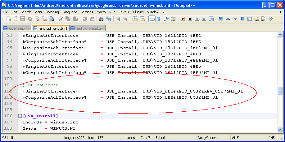
  2. Underneath the section [Google.NTx86], add in the hardware ids you noted down previously as shown below.


    Note: lines that begin with ';' are comment lines.
  3. Also add in the same lines underneath the section [Google.NTamd64].
  4.  Save the file. Close the text editor.
Install the Android tablet driver
  1. If the Found New Hardware Wizard is closed, then you can unplug the tablet. Then plug it again to the USB port.

    The Found New Hardware Wizard appears.
  2. Choose Not this time. Click Next.


  3. Choose Install from a list or specified location (Advanced). Click Next.


  4. Toggle on Search for the best driver in these locations.Toggle on Include this location in the search. Click Browse. Specify the folder location of the file winusb.inf e.g. C:\Program files\android\android-sdk\extras\usb_driver\. Click Next.


    The wizard installs the driver.

  5. Click Finish to complete.


  6. If necessary, you may need to reboot.
If the driver installation is successful, the Device Manager will list the Android ADB Interface underneath the Android Device node when the tablet is plugged in, as shown below. You should be able to connect to the HP Touchpad through the Eclipse IDE. 

Monday, January 21, 2013

How to change between satellite and traffic layers in Google Maps on Android

I wanted to open up a dialog box from the Google Maps View to toggle between the satellite and traffic map layers as shown in the screenshot below.

I used the code snippet below to toggle between the map layers. But it could not toggle between the layers.
 @Override  
 public void onClick(DialogInterface dialog, int which) {  
 // TODO Auto-generated method stub  
 String layer = (String) layers[which];  
 if (layer.compareToIgnoreCase("traffic")==0){  
 _mapView.setTraffic(true);  
 _mapView.invalidate();  
 }  
 else if (layer.compareToIgnoreCase("satellite")==0) {   
 _mapView.setSatellite(true);  
 _mapView.invalidate();  
 }  
 dialog.dismiss();  
 }  

Later, I found out I could resolve the problem by setting the previous layer to false as shown in the snippet below.

 @Override  
 public void onClick(DialogInterface dialog, int which) {  
 // TODO Auto-generated method stub  
 String layer = (String) layers[which];  
 if (layer.compareToIgnoreCase("traffic")==0){  
 _mapView.setSatellite(false);  
 _mapView.setTraffic(true);  
 _mapView.invalidate();  
 }  
 else if (layer.compareToIgnoreCase("satellite")==0) {  
 _mapView.setTraffic(false);  
 _mapView.setSatellite(true);  
 _mapView.invalidate();  
 }  
 dialog.dismiss();  
 }