Friday, August 28, 2009

QC digital terrain model for isolated spikes with color gradients

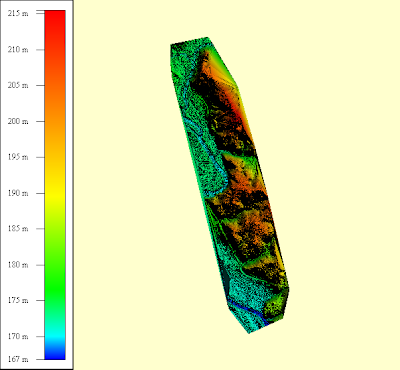
A quick way to find out whether your digital terrain model file has isolated high points or spikes is to display the terrain model with a color gradient from blue to red as shown in the Global Mapper screenshot below.

In this example, the terrain surface is mostly shaded in blue tones. That is a good indication that there are some elevation spikes somewhere in your terrain model.

A screenshot of a digital terrain model file with no high points is shown below. A good terrain surface is shaded evenly with the colors nicely balanced from blue to red as you go from lower elevations to higher elevations.

This is one way to quickly check your digital elevation models for the presence of isolated elevation spikes.

Wednesday, August 26, 2009

Some useful Linux remote commands (to me)

Sometimes I need to dial in to a remote computer running Linux to run some Linux batch processing commands which may take a while to complete. Normally, once you logged out from the remote computer, the processes that you started during the remote login session will be terminated. There is a modifier command that you can use to make sure the processes keep on running even after you logged out.

The modifier command is nohup, which stands for "no hang up". This is how it is used:

$ nohup your_long_process_command &

where your_long_process_command is obviously your long process command name.

Any processing messages printed out by your process would be rerouted to the text file nohup.out.

You can now logged out from the remote computer.

The next time you dial in to check on the status of your process, you can either review the nohup.out file with a text editor or you can run the following command to see whether it is still running in the process list.

$ ps -ef | grep your_long_process_command

If it returns a process list number, then it is still running.


Wednesday, August 19, 2009

Quickly attach xls/csv/dbf files in GeoMedia

GeoMedia allows you to connect to text files via the Text File Data Server connection, which requires you to define a text file server definition file. Although this method is powerful and flexible, it is not easy for users to grasp. There is an alternative quick and easy way in GeoMedia to attach and display the same text files via the Attach as Feature Table function. This function also allows you to display Excel spreadsheets (*.xls) and Dbase files (*.dbf), in addition to CSV text files (*.txt, *.csv). Here are the steps.

In this example, I want to attach the CSV text file shown below in a text editor. It has the standard header in the first line and the comma separated records below that.

  1. In GeoMedia, connect to a Access read/write database.

  2. Select Warehouse > Feature Class Definition.

    The Feature Class Definition dialog box appears.


  3. In the Feature Classes box, click a Access read/write connection e.g. tmp. Click Attach.

    The Attach dialog box appears.


  4. In the Type combo box, choose the type of file you want to attach, e.g. Text. Click Browse.

    The Open dialog box appears.


  5. Browse and select the file you want to attach, e.g. gps.csv. Click Open.

    The Attach dialog box is updated with the selected file.


  6. If you like, change the default name of the target table. Click OK.

    The attach feature table is appended to the Access connection.


  7. Click Close.
From now on, you can display and manipulate the records in the attached file within GeoMedia. For instance, you can select Window > Data Window and display the contents of the file as shown below.

Tuesday, August 4, 2009

Create a GeoTiff image from shape file using FME

I thought I'd try out using FME to create GeoTiff images from vector geometries. It is actually quite straightforward and the trick is to make sure that the fme_color attribute is set to some rgb value either explicitly or through the PenColorSetter transformer. In this simple example, I convert a polygon geometry shape file to a GeoTiff image file.
  1. Using the FME Workbench, create a Shape file to GeoTiff translation workflow as shown in the figure below. Add in the PenColorSetter and ImageRasterizer transformers and connect them up accordingly.


  2. Open up the PenColorSetter Parameters. Define a Pen Color, e.g. red.


  3. Open up the ImageRasterizer Parameters.

  4. In the Rows/Columns or Cell Size field, choose RowsColumns (if you want to set the GeoTiff image file dimensions by cell size, then choose CellSize and define the X and Y Cell Spacing).

  5. In the Number of columns field, enter the horizontal pixel dimensions e.g. 1000.

  6. In the Number of rows field, enter the vertical pixel dimensions e.g. 800.

    The ImageRasterizer Parameters may look like this at this point.


  7. Close the ImageRasterizer Parameters dialog box.

  8. The source and destination coordinate system should be set if you want to create a geo-referenced GeoTiff image file. In the Navigator pane, define the source dataset coordinate system, e.g. LL84 for geographic WGS84.


  9. In the Navigation pane's destination coordinate system parameter, define the destination GeoTiff dataset's coordinate system, e.g. LL84.

  10. Run the translation.

    The GeoTiff image file is generated.
The resultant GeoTiff image file can be opened up in any GIS application software like GeoMedia or Global Mapper as shown below.


Friday, July 3, 2009

Create multiple lines of text with Geomedia functional attributes

GeoMedia's Functional Attributes can be used to create multi-line text geometries from database attribute values. As an example, I have the following database fields label1 and label2 in my database table as shown in the figure below.


I want to form a multi-line text geometry using label1 as the first line and label2 as the second line. The Functional Attributes can be used to form the multi-lines. Here are the steps.
  1. Select Start > All Programs > GeoMedia > GeoMeda. Open an existing workspace.

  2. Select Analysis > Functional Attributes.

    The Functional Attributes dialog box appears.


  3. Click New.

    The Functional Attribute dialog box appears.


  4. Under Categories, click Geometry. Double click CREATETEXTPOINT under Functions.

  5. In the Expression field, form the following string by keying in or double clicking the names under Attributes.

    CREATETEXTPOINT(Input.Geometry, Input.label1+Constant.NewLine+Input.label2, 0)

    Note: + is the string concatenate operator and Constant.NewLine is the new line character.


  6. Click Add. Then click Close.


  7. Click OK.

    The multi-line text point geometry is created in the Map Window.

Wednesday, July 1, 2009

Correct GPS elevation readings for geoid heights with GeoMedia

Intergraph GeoMedia's coordinate system engine can be used to convert your GPS receiver's elevation readings to the correct topographic height taking into account the reference geoid height. Besides GeoMedia, I have not seen vertical datum conversion functions in other software like Global Mapper or Safe FMe but I am sure ESRI ArcGis should have those functions too. For more information about geoid correction for GPS and topographic height, you can visit this site.

As an example of using GeoMedia to convert the GPS measured elevations to topographic height, I use an Excel spreadsheet containing just 2 GPS points as shown below as my source data.


And now, the procedure. There are many ways to read in data in GeoMedia but in this example I chose to attach it as a table in a Microsoft Access database.
  1. Run GeoMedia or GeoMedia Professional and open a read-write connection to a Microsoft Access database.

  2. Select Warehouse | Feature Class Definition.

    The Feature Class Definition dialog box appears.


  3. Select the Access connection e.g. tmp. Click Attach.

    The Attach dialog box appears.


  4. In the Type drop down list, select Excel 97. Click Browse and select the Excel spreadsheet containing the GPS readings.

    The selected spreadsheet name is displayed.


  5. Change the target table name if you like. Click OK.

    The Excel spreadsheet is attached as a table to the Access database connection.


  6. Now make sure the workspace coordinate system is Geographic WGS84 with EGM96 vertical datum. Select View | Coordinate System.

    The GeoWorkspace Coordinate System dialog box appears.


  7. Click OK.


  8. Select Analysis | Geocode Coordinates.

    The Geocode Coordinates dialog box appears.


  9. In the Geocode attributes in field, choose the attached Excel spreadsheet table e.g. gps.

  10. Click Coordinate System.

    The Coordinate System Properties dialog box appears.


  11. Make sure the coordinate system is Geographic WGS84. In the Vertical datum drop down list, select Ellipsoid (geometric).


  12. Click OK.

  13. In the Longitude field, select the Excel spreadsheet column for longitude values e.g. lngdeg.

  14. In the Latitude field, select the Excel spreadsheet column for latitude values e.g. latdeg.

  15. In the Height field, select the Excel spreadsheet column for the GPS elevation readings e.g. gpshgt.


  16. Click OK.

    The geocoded GPS points are displayed in the map window.

We have now corrected the GPS elevation readings. To verify this, just review the Z values of the point features.
  1. Use the Select Tool command and click on one of the GPS points.

    The point is selected and shown in green.

  2. Select Edit | Select Set Properties.

    The Properties dialog box appears.


    Note that the Z value shown is now the topograhic height i.e. the GPS reading minus the geoid height at that location.

Tuesday, June 30, 2009

Append Path variable during installation with Visual Studio

In my previous post, I mentioned that using the Microsoft Visual Studio Setup and Deployment Wizard's Registry Editor to add in your custom application's path to the system path environment variable has an unfortunate side effect - the uninstaller will delete the system path variable.

A better but longer way is to write your own custom action program to add in your custom application's path to the system path environment variable during installation. In the custom action program (I call it AddPath and I use C# in my example code), I call a SetPathVariable function from main as shown below to do the job.

class Program
{
static void Main(string[] args)
{
try
{
//Call this function to add in my custom application's location to the system path variable
SetPathVariable();
}
catch
{
}
finally
{
}
}

The SetPathVariable will read in the AddPath program's command line arguments to find the custom application's location.

#region public methods
public static void SetPathVariable()
{
//Read and place the command line arguments into a string array.
//The custom application path is the first argument.
string[] cmd_args = System.Environment.GetCommandLineArgs();

//Now call this function to append the custom application's folder
//to the system Path environment variable
AppendPathVariable(cmd_args[0]);
}


public static void AppendPathVariable(string appPath)
{
try
{
//Filter custom application's path
string loc = GetPathOnly(appPath);
//Get the current value of the Path environment variable
string Value = System.Environment.GetEnvironmentVariable("Path", EnvironmentVariableTarget.Machine);

//Only append the custom application's path if it is not already in
//the system Path environment variable.
if (Value.ToUpper().Contains(loc.ToUpper()) == false)
{
Value = Value + ";" + loc;
System.Environment.SetEnvironmentVariable("Path", Value, EnvironmentVariableTarget.Machine);
}
}
catch (Exception ex)
{
Console.WriteLine(ex.Message);
Console.WriteLine(ex.StackTrace);
}
}

//This function simply ensures that the input string is a valid
//path string
public static string GetPathOnly(string url)
{
string outputStr = string.Empty;
string ipurl = url;
char[] delimiter = { '\\'};
string[] values = ipurl.Split(delimiter);
for (int i = 0; i <values.Length - 1; i++)
{
if (i == 0)
{
outputStr = values[i];
}
else
{
outputStr = outputStr + @"\" + values[i];
}
}
return outputStr;
}
#endregion
}

In the Setup and Deployment project, you need to add in this AddPath executable in the Custom Actions Commit phase as shown in the figure below.
In addition, you have to set the Arguments property for AppPath to “[OriginalDatabase]<>[TARGETDIR]<>[ComputerName]", as shown below.
Now your installer will be able to add in your custom application's path to the System Path environment variable correctly without having it deleted by the uninstaller.