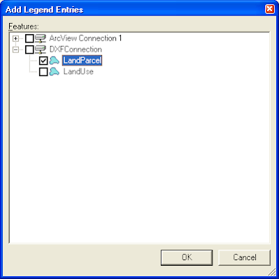
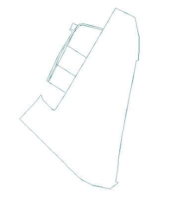
Here are the steps to create the schema file and to connect to the DXF warehouse.
Defining the CAD Server Schema File
- On the Windows desktop, select Start > All Programs > GeoMedia > Utilities > Define CAD Server Schema File.
The Define CAD Server Schema File dialog box appears.
- In the Define CAD Server Schema File dialog box, select File > New.
The New dialog box appears.
- Choose AutoCadTemplate.csd and click New.
The Select Map Files dialog box appears.
- In the Select Map Files dialog box, click New.
The Browse For Folder dialog box appears. - Browse and choose the folder containing your DXF file(s), e.g. D:\Warehouses\dxf\. Click OK.
The Select Map Files dialog box displays the selected folder and any DXF files contained in the folder.
- In the Map files list box, toggle on the DXF file(s). Click OK when done.
The Select Coordinate System Files dialog box appears.
- In the Coordinate system files list box, toggle on the coordinate system file suitable for the DXF data. Click OK.
Note: Prior to this step, you must have created and defined a suitable coordinate system file using the GeoMedia Define Coordinate System File utility.
The Define Feature Class dialog box appears.
- In the Define Feature Class dialog box, click New.
The New dialog box appears. - In the Name field, type in a suitable name for a feature in the DXF data, e.g. LandParcel.
- In the Geometry type list box, toggle on an appropriate geometry type for the feature, e.g. AreaGeometry.
The New dialog box may look like this.
- Click the Graphic Attributes tab.
- Toggle on any Graphic Attribute Name you wish to expose as attributes in GeoMedia, e.g. EntityColor, BlockName, EntityType, etc.

- Click the Criteria tab.
- Toggle on the DXF Attribute Name(s) that defines the current feature and type in the Classification Criteria.
For example, if you have polygons representing land parcels in the DXF file and they are stored uniquely on a DXF layer named as 'LAND_PARCELS', then you would toggle on the LayerName attribute and typed in LAND_PARCELS in the Classification Criteria field.
- Click OK.
The Define Feature Class displays the newly defined DXF feature.
- If you have additional features to define, repeat the previous steps 8 to 15.
- In the Define Feature Class dialog box, click Close.
- In the Define CAD Server Schema File dialog box, select File > Save.
The Save As dialog box appears.
- In the File name field, type in a name for the new CAD Schema definition file, e.g. Dxf.csd.
- Click Save.
- Close the Define CAD Server Schema File dialog box.
You can now connect to the DXF file via the CAD Server Schema in GeoMedia.
- In GeoMedia, select Warehouse > New Connection.
The New Connection dialog box appears.
- In the Connection type list box, select CAD.
- In the Connection name field, type in an appropriate name, e.g. DXFConnection.
- In the CAD Server Schema file field, click Browse and select the schema file you created earlier.
- Click OK.
GeoMedia is now connected to the DXF data warehouse.


1 comment:
very informative post. thank you.
Geospatial Utilities
Post a Comment