Monday, November 14, 2011

C# code snippet to read an Applanix SBET file

The smoothed best estimated trajectory (SBET) file of an air survey flight created and exported by the Applanix PosPac software is a simple binary format. The SBET file is just a series of records with the following double fields, as described by the C# code below:

public class SbetRecord
{
    public double time;    //GPS seconds of week
    public double latRad;    //latitude in radians
    public double lonRad;    //longitude in radians
    public double alt;    //altitude
    public double xVel;    //velocity in x direction
    public double yVel;    //velocity in y direction
    public double zVel;    //velocity in z direction
    public double roll;    //roll angle
    public double pitch;    //pitch angle
    public double heading;    //heading angle
    public double wander;    //wander
    public double xForce;    //force in x direction
    public double yForce;    //force in y direction
    public double zForce;    //force in z direction
    public double xAngRate;    //angular rate in x direction
    public double yAngRate;    //angular rate in y direction
    public double zAngRate;    //angular rate in z direction
}

Then just use a BinaryReader to open up the file and read in the fields as doubles as shown in the code snippet below.
SbetRecord rec = new SbetRecord();
// Open an SBET file for reading...
BinaryReader reader = new BinaryReader(File.Open(@"C:\Temp\sbet1.out", FileMode.Open, FileAccess.Read));
 
// ...read a record...
rec.time = reader.ReadDouble();
rec.latRad = reader.ReadDouble();
rec.lonRad = reader.ReadDouble();
rec.alt = reader.ReadDouble();
rec.xVel = reader.ReadDouble();
rec.yVel = reader.ReadDouble();
rec.zVel = reader.ReadDouble();
rec.roll = reader.ReadDouble();
rec.pitch = reader.ReadDouble();
rec.heading = reader.ReadDouble();
rec.wander = reader.ReadDouble();
rec.xForce = reader.ReadDouble();
rec.yForce = reader.ReadDouble();
rec.zForce = reader.ReadDouble();
rec.xAngRate = reader.ReadDouble();
rec.yAngRate = reader.ReadDouble();
rec.zAngRate = reader.ReadDouble();
 
// ... etc ...

Monday, November 7, 2011

Clip a polygon with another polygon using Global Mapper

In GIS data editing work, it may be useful to clip a polygon with another polygon in a simple boolean operation. Global Mapper can perform the clipping task using the Cut Selected Area(s) from another Area (Add Islands) function. The example below illustrates a simple polygon clipping procedure:
  1. Start Global Mapper. Load or create at least two overlapping polygons.


  2. Press ALT+D.

    The Digitizer Tool is activated.
  3. Move the cursor to the polygon to be used as the clipper. Click on the polygon.

    The polygon is selected.
  4. Press the mouse right button anywhere in the map view.

    A pop up menu appears.

  5. Choose Cut Selected Area(s) from Another Area (Add Islands).

    The prompt appears: Select the Area to use as the Parent for this island, Esc to cancel.
  6. Move the mouse to the polygon to be clipped. Click on the polygon.

    The prompt below appears.
  7. Click Yes.

    The polygon is clipped.

Monday, October 31, 2011

Passing Unicode strings between C# and C/C++ dynamic link libraries

Passing simple data types like int, boolean, double between managed C# code and unmanaged C/C++ code is fairly straightforward. However, passing Unicode strings between them is a little more complicated. To simplify the coding effort, wrapper functions can be written to hide away the complexity as illustrated in the examples below.

Example 1: Passing from C# to C/C++
If the C/C++ function has the following signature (where the second parameter is the Unicode string to be passed to the C++ function):

HRESULT SetGpsData( HANDLE hClient, const char* szNmeaSentence );

Then the following wrapper functions can be used:

[DllImport("myDynamicLinkLib.dll")]
private static extern int SetGpsData(IntPtr hClient, IntPtr szNmeaSentence);
public static int SetGpsData(IntPtr hClient, string szNmeaSentence)
{
    IntPtr pszNmeaSentence = IntPtr.Zero;
    pszNmeaSentence = Marshal.StringToHGlobalUni(szNmeaSentence);
    int hr = SetGpsData(hClient, pszNmeaSentence);
    Marshal.FreeHGlobal(pszNmeaSentence);
    return hr;
}

Inside the wrapper function, the Unicode string has to be copied to unmanaged memory using the Marshal class' StringToHGlobalUni method first and then passed as a pointer to the C/C++ function. Finally, free up the unmanaged memory after you are done with the FreeHGlobal method.

To use the public wrapper function, simply do the following:

IntPtr hClient = IntPtr.Zero;
string szNmea = "$GPGGA,123519,4807.038,N,01131.000,E,1,08,0.9,545.4,M,46.9,M,,*47";
int ret = SetGpsData( hClient, szNmea);

Example 2: Passing from C/C++ to C#
If a C/C++ function has the following signature (where the second parameter is the Unicode string value to be returned by the function):

BOOL GetTheString( HRESULT hr, LPWSTR szName, INT maxChar );

Then the wrapper functions in C# can be written as:

[DllImport("myDynamicLinkLib.dll")]
private static extern bool GetTheString(int hr, IntPtr szName, int maxChar);
public static bool GetTheString(int hr, out string szName)
{
    bool ret = false;
    IntPtr pSzName = IntPtr.Zero;
    pSzName = Marshal.AllocHGlobal(260);
    szName = string.Empty;
    if (hr != 0)
    {
        bool status = GetTheString(hr, pSzName, 260);
        if (status)
        {
            szName = Marshal.PtrToStringUni(pSzName);
        }
    }
    Marshal.FreeHGlobal(pSzName);
    return ret;
}
In this example, inside the wrapper function, unmanaged memory for the Unicode string is allocated first using the Marshal class' AllocHGlobal method. Then the pointer to that memory is passed to the C/C++ function, which will then write the string value in the allocated memory. In managed C# code, the Unicode string value is copied from the unmanaged memory using the PtrToStringUni method. As above, remember to free up the allocated memory using the FreeHGlobal method.

To use this wrapper function, simply do the following:

IntPtr hClient = IntPtr.Zero;
string szFromDLL = string.Empty;
bool ret = GetTheString( hClient, out szFromDLL);

Monday, October 24, 2011

Decompose polygon vertices to points in Global Mapper

In Global Mapper, you can decompose the vertices of selected polygons into standalone point features. The process is basically a two part process - selected one or more polygons. Then select the command, as shown below in detail.

  1.  Start Global Mapper. Load or digitize polygon features.

    The polygon feature(s) are displayed.
  2. Press ALT+D.

    The Digitizer is activated.
  3. Press SHIFT and click on one or more polygons.

    The polygons are selected.

  4. Press the mouse right button in the map view.

    A pop up menu appears.

  5. Choose Advanced Feature Creation Options | Create New Points from Selected Area and Line Features.

    The vertices are converted to point features.

Monday, October 17, 2011

How to align the Facebook "like" button with Twitter and Google +1 buttons

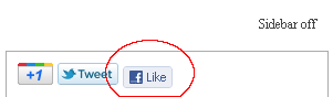
I recently added the Facebook, Twitter and Google Plus social network sharing buttons to a Google Mapplets web page. I found that while the Twitter and Google Plus buttons align properly, the Facebook Like button is shifted slightly below the rest of the buttons. The figure below shows the problem clearly.

After a bit of searching around the Internet, I learnt the problem can be solved by setting the DIV elements containing all the buttons to 1 pixel font-size and to display as inline-block. There is an additional Facebook DIV class element - fb_reset that needs to be displayed as inline only.

The example web page HTML code containing the buttons is shown below.
<div id="social">
    <!-- +1 -->
    <div class="plusone">
    <!-- Place this tag where you want the +1 button to render -->
    <g:plusone size="medium" annotation="none"></g:plusone>
    <!-- Place this render call where appropriate -->
    <script type="text/javascript">
      (function() {
        var po = document.createElement('script'); po.type = 'text/javascript'; po.async = true;
        po.src = 'https://apis.google.com/js/plusone.js';
        var s = document.getElementsByTagName('script')[0]; s.parentNode.insertBefore(po, s);
      })();
    </script>    
    </div>
    <!-- end +1 -->
    <!-- twitter -->
    <div class="twitter">
    <a href="https://twitter.com/share" class="twitter-share-button" data-count="none" data-via="dominoc">Tweet</a><script type="text/javascript" src="//platform.twitter.com/widgets.js"></script>    
    </div>
    <!-- end twitter -->
    <!-- like -->
    <div class="fb-like" data-send="false" data-layout="button_count" data-width="90" data-show-faces="false"></div>
    <!-- end like -->
</div>

The corresponding CSS style sheet to set the DIV elements is shown below:
#sidebar #social {
    margin: 10px;
}    
div .plusone, .twitter, .fb-like {
    font-size: 1px;
    display: inline-block;
}
div .fb_reset {
    display: inline;
} 
With the above style sheet, the buttons are aligned properly as shown below.

Monday, October 10, 2011

Set Coordinate Reference System for a grid file in SAGA GIS

When an ESRI ArcGrid ASCII Grid file without an associated projection file (*.prj) is loaded into SAGA GIS, the grid data will be placed in a plain cartesian X and Y reference frame. If the description of the grid layer is displayed in SAGA GIS, then it will show as Undefined Coordinate System for the Projection as shown below.
SAGA GIS has a function to set the grid file's coordinate reference system; the workflow is shown below.

  1. Select Modules | Projection | Set Coordinate Reference System.

    The Set Coordinate Reference System dialog box appears.

  2. Select the Dialog field. Click the [...] button.

    The Dialog appears.
  3. In the Projection Type field, choose an appropriate projection e.g. Universal Transverse Mercator (UTM).
  4. Click the Projection Settings field. Then click the [...] button.

    The Universal Transverse Mercator dialog box appears.

  5. In  the Zone field, type in a value e.g. 32. Toggle on South if necessary. Click Okay.
  6. If necessary, define any other settings appropriate for the coordinate reference system. Click Okay.
  7. Click the Data Objects Grids field. Click the [...] button.

    The Grids dialog box appears.
  8. Select one or more grid layers on the left e.g. 01. ground. Click the > button. Click Okay.


  9. Click Okay.

    The defined coordinate reference system is assigned to the selected grid layer(s).
  10. Selecting the grid layer and displaying the description shows that the grid layer has been assigned the new projection parameters.

Monday, October 3, 2011

Create polygon centroids in gvSIG

It is possible to use gvSIG to create polygon centroids but this is done indirectly through the use of add-on functionality from the Sextante tool box. Note that the centroid created will be at the geometric center of the polygon, which may lie outside depending on the shape of the polygon. An illustration of how to create the centroids is shown below.


  1. Start gvSIG OADE. Load a polygon layer e.g. States.shp into a map View.


  2. Click the SEXTANTE Toolbox icon in the tool bar.

    The SEXTANTE window appears.

  3. Expand the Algorithms | Tools for polygon layers nodes.


  4. Double click Centroids.

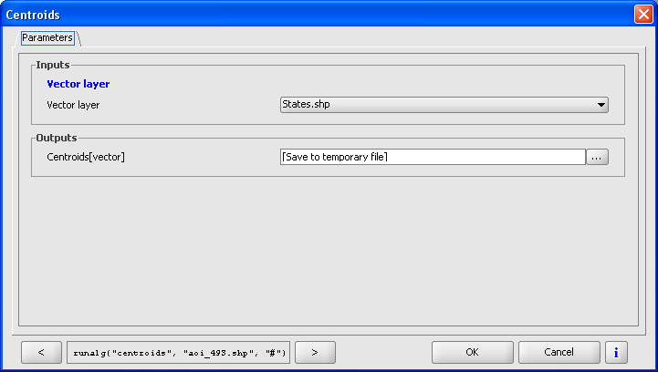
    The Centroids dialog box appears.

  5. In the Vector layer field, choose the polygon layer e.g. States.shp.
  6. Optional. In the Outputs Centroids field, type in the full path and name of the centroids shape file.
  7. Click OK.

    The centroids are created.