Monday, December 19, 2011

Accessing PostGIS database features from gvSIG

The PostGIS spatial database can be accessed by a variety of client software including gvSIG, FME, and even Intergraph's GeoMedia. It is possible to import features from GeoMedia into the PostGIS database and manipulated through an open source software like gvSIG. For instance, the example States feature in the screenshots below was imported to PostGIS via GeoMedia's Export Feature command.

In order for gvSIG to access and manipulate features in PostGIS, a GeoDB connection must be made first as shown below.
  1. Start gvSIG OADE 2010. Create a new View with the desired coordinate system, e.g. Albers Equal Area. Open the view.


  2. Select View | Add Layer.

    The Add Layer dialog box appears.

  3. Click the GeoDB tab.
  4. In the Connection field, click the New Connection button on the right.|

    The Connection Settings dialog box appears.

  5. In the Connection name field, type in a name e.g. PostGISConn1.
  6. In the Driver field, choose PostGIS JDBC Driver.
  7. In the Server URL or IP field, type in the address name or the IP address e.g. 192.168.1.99.
  8. In the Database name field, type in the PostGIS database name e.g. gdotest.
  9. In the User field, type in the database user name e.g. gdouser.
  10. In the Password field, type in the password of the database user e.g. gdouser.
  11. Click OK.

    If the values are correctly filled, the database would be connected to gvSIG. A list of tables appear

  12. In the table list field, toggle on one or more spatial tables e.g. public.states.
  13. Click Ok.

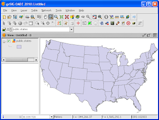
    The selected table(s) are displayed in the View.
Monday, December 12, 2011

Add your own property field to Google Maps polygons

The Google Maps Overlay classes such as the Polygon or Polyline classes have only standard properties including clickable, fillColor, paths, zIndex, etc. In certain circumstances, it is advantageous to extend the overlay classes to include additional user-defined properties such as the polygon title or road name so that the user-defined values can be retrieved when certain events occur - such as a polygon click event.

It is quite simple to extend the class to include your own properties as shown in the example code listing below. Simply add in the property and value when the overlay class is created.

The example code listing below shows how to extend a polygon to include a new property field named html It also illustrate how to retrieve the property value back when the polygon is clicked.


 //...etc...  
 var contentString = "Hello world, this is my new attribute";  
 //Create a new polygon with an additional user defined property: html  
 var leftBot = new google.maps.LatLng(0,0);  
 var leftTop = new google.maps.LatLng(2,0));  
 var rightTop = new google.maps.LatLng(2,2);  
 var rightBot = new google.maps.LatLng(0,2);  
 var polyCoords = [leftBot,     leftTop, rightTop,     rightBot, leftBot];                           
 var poly = new google.maps.Polygon({  
      html: contentString,  
      paths: polyCoords,  
      strokeColor: "#FF0000",  
      strokeOpacity: 0.8,  
      strokeWeight: 2,  
      fillColor: "#FF0000",  
      fillOpacity: 0  
 });                 
 poly.setMap(map);  
 //Add an on polygon click event handler to display the user defined property when clicked  
 google.maps.event.addListener(poly, "click",   
      function (evt){  
           var contentString = this.html;  
           var vertices = this.getPath();  
           var xy = vertices.getAt(0);  
           _infoWnd.setContent(contentString);  
           _infoWnd.setPosition(evt.latLng);  
           _infoWnd.open(map);  
      }  
 );       
 //.... etc....  

Monday, December 5, 2011

How to find out the digitized line directions in gvSIG

Sometimes it is useful to find out the direction the line work was digitized. It is possible to use the labeling function in gvSIG to display an indicator of the line direction as shown in the screenshot below.


The steps to label the line work with "direction" indicators are outlined below.
  1. Start gvSIG OADE 2010. Open a map view and load in a line geometry file e.g. test.shp.


  2. In the legend (TOC) pane, click the line layer. Right click the layer name with the mouse.

    A popup menu appears.
  3. Choose Properties.

    The Layer properties dialog box appears.

  4. Click  the Labeling tab.
  5. Toggle on Enable labeling. In the General field, choose Advanced settings.
  6. In the Method field, choose the Label all features in the same way.
  7. Click the Placement button.

    The Placement properties dialog box appears.

  8. In the Orientation group, choose Follow line.
     
  9. In the Position group, choose On the line. In the Orientation drop down list, choose Line.
  10. In the Along lines field, choose In the middle.
  11. Choose to Place one label per feature part. Click OK.
  12. Click the Properties button.

    The Label class properties dialog box appears.

  13. Click the first row in the Label no. grid. Then click the [...] button.

    The Expression dialog box appears.

  14. In the Expression field, type in "<". Click OK.
  15. Toggle on Label features in this class and choose All features. Click OK.
  16. Click OK.

    The digitized line directions are indicated with the "<" character.

Monday, November 28, 2011

Google Mapplet to readout UTM coordinates

This Google Maps tool was written to show the local Universal Transverse Mercator (UTM) easting and northing values of any clicked point on Google Maps.

To use this tool,
  1. Simply open up any Internet browser and 
  2. Go to http://dominoc925-pages.appspot.com/mapplets/cs_utm.html.
  3. Then click on any location on the map.

    An info window pops up showing the easting and northing values.
If necessary, the Standard Molodensky transformation is used to transform a position between Google Maps' WGS84 datum and the user defined reference datum. The ellipsoid and datum transformation parameters are taken from the University of Colorado site http://www.colorado.edu/geography/gcraft/notes/datum/edlist.html. 

Monday, November 21, 2011

Move a feature to another layer in Global Mapper

It is possible to move an existing geometry feature such as a polygon from one layer to another layer in Global Mapper. It is not as intuitive as it could be but it is certainly possible. Below is an example of moving a polygon from its original layer to a new layer.

  1. Start Global Mapper. Create or load and display some polygon features.

    The polygons are displayed.
  2. Press ALT+D. Press CTRL and click on one or more polygon.

    The polygon(s) are selected.
  3. Press the mouse right button anywhere inside the map view.

    A pop up menu appears.
  4. Choose Edit Selected Features.

    The Modify Selected Area Features dialog box appears.
  5. In the Feature Layer drop down list, choose another layer to move to. If a new layer is wanted, then choose Create New Layer for Feature. Press OK.

    The Enter Layer Name prompt appears.
  6. Type in a layer name, e.g. MyNewLayer. Press OK.

    The selected polygons are moved to the new layer.
  7. Press ALT+C.

    The Overlay Control Center dialog box appears.
  8. Toggle on/off the new layer MyNewLayer.

    The polygons on MyNewLayer are displayed/hidden.

Monday, November 14, 2011

C# code snippet to read an Applanix SBET file

The smoothed best estimated trajectory (SBET) file of an air survey flight created and exported by the Applanix PosPac software is a simple binary format. The SBET file is just a series of records with the following double fields, as described by the C# code below:

public class SbetRecord
{
    public double time;    //GPS seconds of week
    public double latRad;    //latitude in radians
    public double lonRad;    //longitude in radians
    public double alt;    //altitude
    public double xVel;    //velocity in x direction
    public double yVel;    //velocity in y direction
    public double zVel;    //velocity in z direction
    public double roll;    //roll angle
    public double pitch;    //pitch angle
    public double heading;    //heading angle
    public double wander;    //wander
    public double xForce;    //force in x direction
    public double yForce;    //force in y direction
    public double zForce;    //force in z direction
    public double xAngRate;    //angular rate in x direction
    public double yAngRate;    //angular rate in y direction
    public double zAngRate;    //angular rate in z direction
}

Then just use a BinaryReader to open up the file and read in the fields as doubles as shown in the code snippet below.
SbetRecord rec = new SbetRecord();
// Open an SBET file for reading...
BinaryReader reader = new BinaryReader(File.Open(@"C:\Temp\sbet1.out", FileMode.Open, FileAccess.Read));
 
// ...read a record...
rec.time = reader.ReadDouble();
rec.latRad = reader.ReadDouble();
rec.lonRad = reader.ReadDouble();
rec.alt = reader.ReadDouble();
rec.xVel = reader.ReadDouble();
rec.yVel = reader.ReadDouble();
rec.zVel = reader.ReadDouble();
rec.roll = reader.ReadDouble();
rec.pitch = reader.ReadDouble();
rec.heading = reader.ReadDouble();
rec.wander = reader.ReadDouble();
rec.xForce = reader.ReadDouble();
rec.yForce = reader.ReadDouble();
rec.zForce = reader.ReadDouble();
rec.xAngRate = reader.ReadDouble();
rec.yAngRate = reader.ReadDouble();
rec.zAngRate = reader.ReadDouble();
 
// ... etc ...

Monday, November 7, 2011

Clip a polygon with another polygon using Global Mapper

In GIS data editing work, it may be useful to clip a polygon with another polygon in a simple boolean operation. Global Mapper can perform the clipping task using the Cut Selected Area(s) from another Area (Add Islands) function. The example below illustrates a simple polygon clipping procedure:
  1. Start Global Mapper. Load or create at least two overlapping polygons.


  2. Press ALT+D.

    The Digitizer Tool is activated.
  3. Move the cursor to the polygon to be used as the clipper. Click on the polygon.

    The polygon is selected.
  4. Press the mouse right button anywhere in the map view.

    A pop up menu appears.

  5. Choose Cut Selected Area(s) from Another Area (Add Islands).

    The prompt appears: Select the Area to use as the Parent for this island, Esc to cancel.
  6. Move the mouse to the polygon to be clipped. Click on the polygon.

    The prompt below appears.
  7. Click Yes.

    The polygon is clipped.