Thursday, December 17, 2009

Flagging intersection points with elevation differences

Typical GIS applications have the capability to determine unbroken intersections but only from the perspective of a 2D plane i.e. as if the spatial intersection analysis is done only after the line work is projected entirely onto the 2D plane; if the line work has a elevation or Z component, then the Z component is ignored entirely in the analysis. In 3D GIS applications like terrain modeling, sometimes it is useful to be able to determine the elevation difference of the line work at the point of intersection. If one spatial feature represents a lake, then a river line feature flowing out of the lake should have the same elevation at the point of intersection. It would be useful to be able to flag the intersection points that have elevation differences.

In the example dataset below, there are a few line features with different elevation values - the values are labelled along the line work. All of them are at 0 elevation except for one, which is on 10 elevation.

We want to flag out the intersection point where there is a difference in elevation. One of the tools that can help us perform this is Safe FME. FME has some transformers that you can string together to perform the flagging of intersection points with elevation differences.

  1. Run FME Workbench. Add in a Source Dataset e.g. lines.shp. Add in a Destination Dataset e.g. flags.shp.

  2. Drag and drop the Intersector, Matcher, Counter Transformers onto the Main pane. Connect them up as shown in the figure below.


    Note: the Counter transformer is used to simply count the number of flags.

  3. Open up the Intersector transformer's Parameters. The settings should be set as shown below.


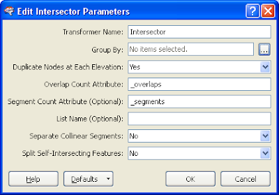
    Note: Duplicate Nodes as Each Elevation should be set to Yes. Then when an elevation difference is detected at the point of intersection, the Intersector transformer will output 2 nodess.

  4. Open up the Matcher transformer's Parameters.The settings should be set as shown below.


    Note: The Matcher will find(match) all duplicate nodes i.e. the nodes that have elevation differences. 

  5. Run the translation.

    The intersection points where there are elevation differences are flagged (shown as a red cross below).


Tuesday, December 15, 2009

Global Mapper Snapping to Line Work

Snapping to existing points, lines and polygons is important while digitizing. Knowing how Global Mapper handles snapping can help improve the data collection work. Sometimes, you may want to snap only to the vertices. At other times, you may want to snap along the line work. And sometimes, you may not want to snap at all.

Setting the Snap Mode
The snapping mode of Global Mapper can be set using the Configuration dialog box

  1. Select Tools > Configure.

    The Configuration dialog box appears.


  2. Click the tab Vector Display.

  3. In the list box, scroll down until the Only Snap to Area and Line Vertices by Default setting is shown.

  4. Depending on your situation, toggle on or off the Only Snap to Area and Line Vertices setting.

    Note: the keyboard shortcut V behavior would be reversed depending on this setting.

  5. Click OK.

    The snapping mode is set.

Using Snapping with Only Snap to Area and Line Vertices by Default off
  1. Digitize a new line and bring the cursor near to a line or polygon as shown below.

    The new line snaps on the line work and vertices of line or polygon.


  2. Press down and hold V.

    The new line will snap only to the vertices of the line or polygon.

  3. Now press down and hold ALT.

    The new line will not snap to anything.

Using Snapping with Only Snap to Area and Line Vertices by Default on


  1. Digitize a new line and bring the cursor near to a line or polygon.

    The new line snaps only to the vertices.


  2. Press down and hold V.

    The new line snaps on the vertices and along the line work.

  3. Press down and hold ALT.

    The new line will not snap to anything.


While digitizing lines, polygons and points in Global Mapper, you will probably want to snap to existing vectors' vertices, on the existing vectors' line work, or not at all.

Saturday, November 28, 2009

Export GeoMedia features and queries to ASCII text file

There is a useful extension to GeoMedia on the Intergraph support web site to unload geometry and attribute information to ASCII text files; it's called the ASCII Unloader. It is free but you need to login first before you can download and install the extension. I use if fairly frequently to take GeoMedia features and queries into another software package like Global Mapper. Once the ASCII Unloader extension is installed, there would a new ASCII Unloader entry to the Extensions pulldown menu within GeoMedia or GeoMedia Professional as shown below.

Using the ASCII Unloader is straightforward and the steps are generally self-explanatory as described below.
  1. In GeoMedia, select Extensions > ASCII Unloader.

    The ASCII Unloader - Output File Format dialog box appears.


  2. In the Features/Query to Unload drop down list, choose the desired feature or query e.g. Interstates feature.

  3. Next, in the Output filename field, click Browse.

    The Save Output ASCII File dialog box appears.

  4. Type in the output filename e.g. C:\Warehouses\Interstates.txt.Click Save.


  5. At this point, you can click Next if the default Output File Format settings are okay. Otherwise, you simply go to the appropriate fields and change e.g. from Comma Delimited to Space Delimited, or toggle on the Field names on first line, etc. A sample of how the changes affect the output file is shown in the Quick View box.

  6. Click Next.

    The Attributes to Output appear.


  7. In the Available attributes list, double click on the attributes you want to output.

    The attributes are selected and displayed in the Selected attributes list.

  8. In the Units & Precision list, select the type of the coordinates e.g. Projection.

  9. In the Available coordinates list, double click on the type to output e.g. Easting and Northing.

    The items are displayed in the Selected coordinates list.


  10. At this point, to see a sample of how the output file will look like, click View First 25 Records.

    The View Format dialog appears.


  11. Click Close. If necessary, change any settings you want.

  12. Click Apply.

    The ASCII text file is created.


Friday, November 20, 2009

Flagging dangles (free end points) with FME


FME has many transformers that you can mix and match to perform almost any kind of spatial data validation. A common task in data validation is to identify unconnected end points (commonly known as dangles or free end points) in the line work. In the sample data shown below, there are 5 dangles among the 8 vertices of the line work.

To get FME to identify the dangles, I used the Workbench to define the following transformation.

The steps are described below.
  1. Start the FME Workbench and open a blank workspace.

  2. Select Source Data > Add Dataset to add in a source dataset.

    For this example, I added in a ESRI shape file as the source dataset.


  3. Select Destination Data > Add dataset to add in a destination dataset.

    I chose to output the dangle flags as ESRI Shape point file.


  4. Drag and drop the following transformers onto the workbench:
    - CoordinateFetcher (2 times)
    - GeometryRemover
    - 2DPointAdder
    - Matcher

  5. Connect the transformers with the source and destination datasets as shown below.


  6. Open up the first CoordinateFetcher's properties.In the Index field, type in 0. Click OK.


    Note: this transformer will extract the line work's first vertex into the fields _x, _y, and _z.

  7. Open up the second CoordinateFetcher's properties. In the Index field, type in -1. Click OK.


    Note: this transformer will extract the last vertex of the line feature into the fields _x, _y, _z.

  8. Open up the 2DPointAdder transformer's properties. In the X-Value field, choose _x. In the Y-Value field, choose _y. Click OK.


    Note: the 2DPointAdder will create a new point from the _x and _y fields.

  9. Open up the Matcher transformer's properties.In the Match Geometry field, choose 2D.

    Note: In this example, in the Attribute(s) to match field, I chose _x, _y but this is redundant because the 2D point geometry already has the _x and _y coordinates. This field can be left blank.


  10. Run the translation.

    The dangles are created and flagged as red crosses below.


Friday, November 6, 2009

Finding out the digitized direction with a line style

In some GIS applications, it is necessary for the lines to be digitized in a certain direction. For example, in terrain modelling, lines representing drainage lines should be digitized from up to downstream. A simple trick to find out the direction of the digitized lines is to display an arrow head. I found Global Mapper to be very easy to assign a directional arrow line style to line features. All you have to do is define a new line type with the directional arrow style, then assign the line type to your line features.

  1. In Global Mapper, select Tools > Configure.

    The Configuration dialog box appears.


  2. Click the Line Styles tab if it is not active. Click New Type.

    The Setup Line Type Information dialog box appears.

  3. In the Type Name field, type in a name e.g. DigitizeDirection.

  4. In the Style drop down list, scroll down with the arrow down key and observe the sample display. Choose the style that has the arrow pointing to the right, e.g. Solid with Arrow P... (Sorry the name is too long to read from the dialog box).


  5. Click OK.

    The new line type is added.


  6. Click OK.

Now you can assign this line type to new or existing line features. If you digitize a new line feature, the following dialog box will pop up at the end of the digitizing.

In the Feature Type drop down list, choose the new line type created earlier e.g. DigitizeDirection. Click OK. As shown in the figure below, the line feature is stylized with an arrow head pointing in the digitized direction.


If the direction is incorrect, then you need to reverse the order of the line feature's vertices.

Friday, October 30, 2009

Flagging intersection points between 2 features with FME

It seems to be easier to fix rather than flag unbroken intersection points between two feature layers. It took me a little while longer to flag the unbroken intersection points using FME transformers. The screenshot below shows two shape file layers - lakes (blue color fill) and rivers (red). I wanted to flag the intersecting points between the lake polygons and the river lines.

I did the following.


Define the two source datasets
  1. Start up FME Workbench. Choose Create a blank workspace.

  2. Select Source Data > Add Dataset.

    The Add Source Dataset dialog appears.
  3. In the Format field, choose ESRI Shape. In the Dataset field, click the browse [...] button.


  4. Select both the lake.shp and river.shp files. Click Open.

    The Add Source Dataset may look like this.


  5. Click OK.

    The Select Feature Types dialog box appears.


  6. Click OK.

    The two selected shape files are added to the workspace.

Define the destination dataset
  1. Select Destination Dataset > Add Dataset.

  2. In the Format field, select ESRI Shape. In the Dataset field, define the output folder e.g. C:\temp\out\.

    The Add Destination Dataset dialog box may look like this.
  3. Click OK.

    The message below appears.


  4. Click Yes.

    The Feature Type Properties dialog box appears.

  5. In the Feature Type Name field, type in intersect_flag. In the Allowed Geometries, choose shape_point.

    The Feature Type Properties dialog box may look like this.


  6. Click User Attributes tab.

  7. Define an attribute ID with Data Type number and Width 2.

    The Feature Type Properties dialog box may look like this.


    Note: id will simply be a counter storing running numbers of flags.

  8. Click OK.

    The source and destination datasets appear on the workspace.
Add in the transformers and define the flow
  1. Drag and drop the following transformers onto the workspace:
    1. Intersector
    2. Coordinate Fetcher (twice)
    3. Geometry Remover (twice)
    4. Aggregator
    5. Tester
    6. 2DPointAdder
    7. Counter

  2. Connect the source and destination datasets with the transformers as shown in the figure below.


  3. Open up the first Coordinate Fetcher transformer's properties.


    Note 1: Index 0 means fetch the first coordinate.
    Note 2: After the Intersector transformer has done its job, the output features are broken up at the point of intersections. The intersection points must therefore be at either ends.

  4. Open up the second Coordinate Fetcher transformer's properties.


  5. In the Index field, type in -1.

    Note: -1 means fetch the last coordinate.

  6. Open up the Aggregator transformer's parameters.


  7. In the Group By field, browse and select the fields or type in the string _x _y.

  8. In the Count Attribute (Optional) field, type in _count.

  9. Open up the Tester transformer's parameters.


  10. Define the test _count > 2 as shown above.

  11. In the Pass Criteria field, choose One test must pass.

    Note: At the intersection points, there must be more than two points. Anything less is either free end points or singly connected points. 

  12. Open the 2DPointAdder transformer's parameters.

  13. In the X Value field, choose _x. In the Y Value field, choose _y.

  14. Open up the Counter transformer's parameters.


  15. In the Count Output Attribute field, type in id. In the Count Start field, type in 1.

    Note: the Count Output Attribute field should be the same name as the destination dataset's attribute field.

  16. Run the translation.

    The intersection points are flagged as numbered points as shown in the screen shot below.

Note that this Intersector transformer method works based on line work intersection only. If the line work sits entirely within the area polygons, there would be no line intersection and therefore no flags.

Thursday, October 22, 2009

Fixing linework intersections using FME's Intersector transformer


I am looking into using FME for performing data validation and quality assurance of some digitized line work. I found a  rich set of transformers for this purpose. One of the data cleaning task that I want to do is to break the line work at the point of intersection. The transformers that can do this are the Intersector and the MRFClean transformers. A more specialized variant of the Intersector is the SelfIntersector transformer.

I gave the Intersector transformer a try on a test case shape file dataset.. I put in a few cases: (1) a self-intersecting line, (2) two intersecting lines, and (3) two overlapping or duplicate lines as shown below.

The Intersector transformer has a few options. For self-intersecting line work, you have the option of getting the transformer to break the line work for you or you can leave it as it is. I would prefer to delegate the breaking of the self-intersecting line work to the SelfIntersector transformer as I would be able to differentiate it from the other cases.

For line work with overlapping segments, the Intersector transformer has the option to output as a merged line work or as separate segments. I would prefer the merge option.

To fix the digitized line work using the Intersector transformer, I used the following steps.
  1. Start up the FME Workbench and choose to use the Workspace Wizard.

  2. In the Wizard, specify ESRI Shape as the source format and choose the input shape file.

  3. Specify ESRI Shape as the destination format

  4. Drag the Intersector transformer from the Transformers pane onto the Main pane. Connect the transformer with the source dataset and the dataset as shown in the screen shot below.


  5. Open up the Destination dataset's Feature Type Properties.Click User Attributes tab. Add in 2 number attributes - _overlaps and _segments as shown below. Click OK.


  6. Open up the Intersector's Parameters. Review the parameters. Click OK.


    Note 1: If Split Self-Intersecting Features is set to No, then self-intersecting line work will not be fixed.
    Note 2: If Separate Collinear Segments is set to No, then overlapping segments in the line work will be fixed and merged
    .

  7. Run the translation.

    The dataset is transformed and fixed.
The results are shown in the screenshots below. 
For the overlapping segments, the Intersector has merged into a single geometry. The _overlaps attribute is set to 2 since 2 overlapping segments were merged into 1. 


For intersecting line work, the Intersector transformer has broken them up into separate segments at the point of intersection. For each segment, the _segments attribute is set to 2 for the number of segments created.


The self-intersecting geometry is left as it is - unfixed because the relevant Intersector parameter was set to No.
The Intersector transformer works quite well for my purpose. It also works on polygon line work as well as 3-D datasets. For 3-D line work, it will optionally create one or two nodes at the point of intersection. The only thing left for me to do is to create some mapping file and scripts to generalize the source and destination dataset definitions.