Monday, May 27, 2013

Optimize aligned aerial photo images tip

Agisoft Photoscan is a software application that can be used for generating orthophoto mosaic images from aerial photographs using structure from motion (SFM) techniques. As part of the procedure of creating orthophotos, the aerial photographs must go through a photo alignment process. Sometimes the alignment process can result in odd orientations; an example is shown below, where the cameras seem oriented at 45 degrees from the horizontal.

It is possible to correct this by running the Optimize command from the Ground Control pane as shown in the screenshot below.

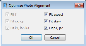
The following dialog will appear when the Optimize command is clicked. Click OK.

Run the Optimize command as many times as required until the orientation appear correct or there is only minor changes in the camera and point cloud. The screenshot below shows the optimized or corrected cameras and point cloud.

Monday, May 20, 2013

Android App for monitoring natural disasters

You can monitor natural disasters around the world, as published by the Global Disaster Alert and Coordination System - www.gdacs.org with this Android App. The app shows the latest natural disasters like earthquakes, volcano eruptions, tropical cyclones, tsunamis and floods as color coded icons in a list as well as on a Google Maps backdrop; the icon colors indicate the alert level - green, orange, and red. The icon will look more transparent the older the event was published. 

The list view can be used to sort the natural disaster events according to the date time, region, and disaster type. 

Clicking on an item on the list will bring up more details about the disaster event.

To view more information about the event, clicking the Browser button will open up the source GDACS web page with more details, as shown below.

On the other hand, clicking the Map button will bring up a Google Map view of the event, as shown below.


Download the app from the Google Play store. 
Get it on Google Play

Monday, May 13, 2013

Export a LibreOffice Base table as a CSV file

Previously I use Microsoft Access to manipulate and export out table data as comma separated values (CSV) files. I decided to use LibreOffice Base to do the same thing. It wasn't difficult to create CSV files in LibreOffice but the concept is different than Microsoft Office's. In LibreOffice, you have to create the text file document first before dragging the source table into the document. It took me a while to figure this out. The following steps illustrate how to do it.

  1. Click Start | All Programs | LibreOffice 4.0 | LibreOffice.

    LibreOffice appears.

  2. Click Text Document.

    A blank Writer document appears.

  3. Press F4.

    The Data Source pane appears.

  4. Expand the database nodes until the desired table e.g. biblio, is visible.


  5. Drag and drop the table onto the blank document.

    The Insert Database Columns dialog box appears.

  6. Toggle on Text.
  7. Select a Database column to export, e.g. Booktitle. Then click >. Repeat for additional columns, e.g. Author and Publisher.
  8. Edit the format string to include a comma or any other delimiter between the columns.


  9. Click OK.

    The table data is placed on the document.

  10. Select File | Save As.

    The Save As dialog box appears.

  11. Type in a file name e.g. mycsvfile. Choose the type as Text. Click Save.

    The CSV file is created.

Monday, May 6, 2013

Import a CSV file into LibreOffice Base

After using Microsoft Access for many years, I decided to give LibreOffice Base a spin. One of the usual task I do with Access is to import a Comma Separated Values (CSV) file into an Access *.mdb database, where I could run some SQL queries on it. I wanted to do the same thing using Base. It turned out that I could copy and paste the CSV file via a LibreOffice Calc spreadsheet, but a better way is to simply open the CSV file directly, as shown below.

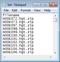
The example CSV file is shown in the screenshot below.


  1. From the Start button, select All Programs | Libre Office 4.0 | LibreOffice Base.

    The Database Wizard appears.

  2. Toggle on Connect to an existing database. Choose Text. Click Next.
  3. In the Path to text files field, click Browse. Select the folder containing the CSV file, e.g. D:\Temp\myfolder\. Click OK.


  4. If necessary, choose the CSV type e.g. Plain text files (*.txt). Choose the CSV separator formats. Click Next.


  5. Click Finish.

    The Save As dialog box appears.
  6. Type in a new file name, e.g. D:\Temp\csv.odf. Click Save.

    The database is created and the CSV file can be seen as a table.


    Note: this CSV database is read-only. 
  7. Now, create or open up an existing Base database, e.g. New database.odf in another window.


  8. Simply drag and drop the CSV table to the newly opened Base window's Tables icon or pane.

    The Copy table dialog box appears.

  9. Optional. In the Table name field, type in a new name.
  10. Click Next.

    The Apply columns appear.

  11. Click the >>.

    All the columns are moved to the right.
  12. Click Next.


  13. Optional. Type in a new field name and change the type or length if necessary.
  14. Click Create. Optional. When prompted to create a primary key, click Yes to create or No to ignore.

    The CSV file is imported into the Base database.

Monday, April 29, 2013

How I build Boost for 64 bit Windows

I decided to build liblas binaries for 64 bit Windows since I could not easily find the 64-bit binaries. One of the prerequisites include boost. However, I had some difficulty getting 64-bit Boost binaries and header files, and the official Boost 64 bit installer seems to have x86 libraries included somehow causing me linking errors while building liblas. So I decided to compile Boost for x64 myself for liblas. The following steps are what I did to get Boost to compile.

  1. Download the latest Boost source code from Sourceforge http://sourceforge.net/projects/boost/files/boost/. Extract the files to a folder e.g. C:\Work\src\boost_1_52_0\.
     
  2. On the Windows desktop, select Start | All Programs | Microsoft Visual Studio 2010 | Visual Studio Tools | Visual Studio x64 Win64 Command Prompt.

    The Visual Studio x64 Win64 Command Prompt appears.
  3. In the Command Prompt, change directory to the extracted Boost source code folder e.g.

    C:\> cd \Work\src\boost_1_52_0
  4. In the Command Prompt, run the bootstrap.bat.

    C:\> bootstrap.bat

    Bootstrapping is done.
  5. In the Command Prompt, run b2.exe.

    C:\> b2 --toolset=msvc-10.0 architecture=x86 address-model=64 stage

    The Boost C++ libraries are built.

Monday, April 22, 2013

Create a rounded border around a layout of an Android Activity

A rounded border can be easily created around a layout in an Android Activity. An example of how it looks like is shown in the screenshot below.


To define a rounded border drawable using the Android Development Toolkit, in Eclipse, the following steps can be done:

Create a new Android drawable XML file
  1. In the Package Explorer pane of Eclipse, right click on the drawable folder.

    A pop up menu appears.

  2. Choose New | Android XML File.

    The New Android XML File dialog box appears.


  3. In the File field, type in the name of the drawable XML file e.g. myborder.xml.
  4. In the Root Element list, choose shape. Click Finish.

    The file is created and the following code is displayed in Eclipse. 

<?xml version="1.0" encoding="utf-8"?>
<shape xmlns:android="http://schemas.android.com/apk/res/android" >

 
</shape>

Edit the drawable Android XML file
  1. In the Eclipse code editor, type in the following to define the rounded border shape.


    <?xml version="1.0" encoding="utf-8"?>
    <shape xmlns:android="http://schemas.android.com/apk/res/android"> 
    <stroke 
    android:width="1dip" 
    android:color="@android:color/darker_gray" /> 
    <solid 
    android:color="@android:color/background_dark" /> 
    <padding 
    android:left="7dip" 
    android:top="7dip" 
    android:right="7dip" 
    android:bottom="7dip" /> 
    <corners 
    android:radius="6dip" /> 
    </shape>


  2. Save the code.

Using the drawable Android XML file in a layout

When editing the layout XML of an Activity, the newly created rounded border drawable can be referenced and used. For example, in the LinearLayout element, the android:background attribute can be set to the myborder drawable created previously, as shown in the code snippet below.


<LinearLayout 
android:orientation="vertical"
android:background="@drawable/border_rounded_corner"
android:layout_width="wrap_content"
android:layout_gravity="center_horizontal"
android:layout_height="wrap_content">
<TextView
android:layout_width="wrap_content"
android:layout_height="wrap_content"
android:layout_gravity="center_horizontal"
android:text="GPS Week"
/>
<RelativeLayout 
android:orientation="horizontal"
android:layout_gravity="center_horizontal"
android:layout_height="wrap_content"
android:layout_width="wrap_content">

<kankan.wheel.widget.WheelView
android:id="@+id/digit4GpsWeek"
android:padding="0dip"
android:layout_width="wrap_content"
android:layout_height="wrap_content"            
/>
<kankan.wheel.widget.WheelView
android:id="@+id/digit3GpsWeek"
android:padding="0dip"
android:layout_width="wrap_content"
android:layout_height="wrap_content"
android:layout_toRightOf="@id/digit4GpsWeek"
/>
<kankan.wheel.widget.WheelView
android:id="@+id/digit2GpsWeek"
android:padding="0dip"
android:layout_width="wrap_content"
android:layout_height="wrap_content"
android:layout_toRightOf="@id/digit3GpsWeek"
/>
<kankan.wheel.widget.WheelView 
android:id="@+id/digit1GpsWeek"
android:padding="0dip"
android:layout_width="wrap_content"
android:layout_height="wrap_content"
android:layout_toRightOf="@id/digit2GpsWeek"
/>
</RelativeLayout>
<!-- etc -->
</LinearLayout>

The corresponding resultant Activity may look like the screenshot below.

Monday, April 15, 2013

Using the NetTopologySuite to read and write Shapefiles in C#

I was looking for a .NET library to use to read and write Shapefiles without using unmanaged dynamic link libraries. I found quite a few that could read but not write Shapefiles. In the end, I found the NetTopologySuite at http://code.google.com/p/nettopologysuite/ to suit my requirements the best.

The following code snippet show how to use the library's ShapefileDataReader to read a Shapefile. In the example, all the database records and the Shape geometries are read into a features collection.


using GisSharpBlog.NetTopologySuite.Features;
using GisSharpBlog.NetTopologySuite.Geometries;
using GisSharpBlog.NetTopologySuite.IO;
using GeoAPI.Geometries;

...etc....

GeometryFactory factory = new GeometryFactory();
ShapefileDataReader shapeFileDataReader = new ShapefileDataReader(shpFilename, factory);
 
//Display the shapefile type
ShapefileHeader shpHeader = shapeFileDataReader.ShapeHeader;
Console.WriteLine(string.Format("Shape type: {0}", shpHeader.ShapeType));
 
//Display the min and max bounds of the shapefile
IEnvelope bounds = shpHeader.Bounds;
Console.WriteLine(string.Format("Min bounds: ({0},{1})", bounds.MinX, bounds.MinY));
Console.WriteLine(string.Format("Max bounds: ({0},{1})", bounds.MaxX, bounds.MaxY));
 
//Display summary information about the Dbase file
DbaseFileHeader header = shapeFileDataReader.DbaseHeader;
Console.WriteLine("Dbase info");
Console.WriteLine(string.Format("{0} Columns, {1} Records", header.Fields.Length, header.NumRecords));
for (int i = 0; i < header.NumFields; i++)
{
DbaseFieldDescriptor fldDescriptor = header.Fields[i];
Console.WriteLine(string.Format("   {0} {1}", fldDescriptor.Name, fldDescriptor.DbaseType));
}
 
//Reset the pointer to the start of the shapefile, just in case
//shapeFileDataReader.Reset();
 
//Read through all records of the shapefile (geometry and attributes) into a feature collection 
ArrayList features = new ArrayList();
while (shapeFileDataReader.Read())
{
Feature feature = new Feature();
AttributesTable attributesTable = new AttributesTable();
string[] keys = new string[header.NumFields];
IGeometry geometry = (Geometry)shapeFileDataReader.Geometry;
for (int i = 0; i < header.NumFields; i++)
{
DbaseFieldDescriptor fldDescriptor = header.Fields[i];
keys[i] = fldDescriptor.Name;
attributesTable.AddAttribute(fldDescriptor.Name, shapeFileDataReader.GetValue(i));
}
feature.Geometry = geometry;
feature.Attributes = attributesTable;
features.Add(feature);
}
//Close and free up any resources
shapeFileDataReader.Close();
shapeFileDataReader.Dispose();

It is important to free up any resources used by calling the Close and Dispose methods, especially if you want to apply any file based operations e.g. deleting or renaming onto the Shapefile.

The following screenshot shows an example output from the code snippet.
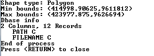

The ShapefileDataWriter class can be used to create a Shapefile. It seems that the class can only create new Shapefiles and there are no methods append to an existing Shapefile. The following code snippet shows how to write features with geometry and attributes into a Shapefile.


//Create a new shapefile from features
GeometryFactory outGeomFactory = new GeometryFactory();
//The constructor will append a ".shp" extension to the input filename so the 1st argument should not have an extension at all
string outShpFilenameNoExt = Path.Combine(Path.GetDirectoryName(outShpFilename), Path.GetFileNameWithoutExtension(outShpFilename));
ShapefileDataWriter writer = new ShapefileDataWriter(outShpFilenameNoExt, outGeomFactory);
DbaseFileHeader outDbaseHeader = ShapefileDataWriter.GetHeader((Feature)features[0], features.Count);
writer.Header = outDbaseHeader;
writer.Write(features);