Showing posts with label ArcGis. Show all posts

Monday, March 12, 2012

C# code to determine if the polygon vertices are in the clockwise direction

In some GIS polygon data formats such as the ESRI shape file format, the holes of a polygon are stored in the counter-clockwise direction while the outer polygon is stored in the clockwise direction. If you are writing a program to read a polygon geometry containing holes, it may be necessary to determine the holes by checking whether the vertices are in the counter-clockwise or clockwise direction.

The C# code snippet below is useful to determine whether the vertices of a polygon are in the clockwise direction or counter clockwise direction. Simply pass in the polygon vertices into the function as an array of PointF structures where the first and last member of the array are the same point. The function will return true if the vertices are in the clockwise direction and false if they are in the counter-clockwise direction.


private bool IsClockwisePolygon(PointF[] polygon)
{
bool isClockwise = false;
double sum = 0;
for ( int i = 0; i < polygon.Length-1; i++)
{
sum += (polygon[i + 1].X - polygon[i].X) * (polygon[i + 1].Y + polygon[i].Y);
}
isClockwise = (sum > 0) ? true : false;
return isClockwise;
}

Monday, January 2, 2012

Google Gadget for creating ESRI World Files


Note: A WebApp version of this Google Gadget will be up in a short while to replace this gadget.

The ESRI World file is a text file used to georeference a corresponding image file. A detailed description of the format can be found in this Wikipedia page http://en.wikipedia.org/wiki/World_file.

Recently I had to create ESRI World files for hundreds of aerial photographs, each having different origin, resolution and orientation. As a result of that exercise, I learnt enough about the World File format to create this Google Gadget.

This gadget can help to create the world files given the following input parameters:
  1. X coordinate of the upper left pixel in ground units,
  2. Y coordinate of the upper left pixel in ground units,
  3. Size of the pixel in the X-axis direction in ground units,
  4. Size of the pixel in the Y-axis direction in ground units,
  5. Rotation angle in degrees of the image from North (clockwise is positive) 
Just fill in the required input, click the button and copy and paste the results into a world file, which must be named according to the type of image file. For example, the World file should have the file extension of .tfw for associating with TIFF images.


Monday, April 11, 2011

Load and Display an ESRI ArcGrid ASCII file in gvSIG

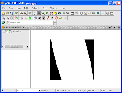
gvSIG can load and display DEMs in ESRI ArcGrid ASCII format. However, an ArcGrid file I loaded was displayed in gvSIG but the result was not what I expected. See the screen shot below.

After exploring the gvSIG interface, I figured out that the default void or no data value gvSIG was expecting was different from what I had in my ArcGrid ASCII file; it seems that gvSIG does not use the NODATA keyword in the ArcGrid file. To get around this, I had to change the void value gvSIG is expecting to match my data and all would be well.

If you find your DEM file is not displaying as you expected, then the following steps might help.

Load an ESRI ArcGrid ASCII file
  1. Start up gvSIG. Open a View.


  2. Select View | Add Layer.

    The Add layer dialog box appears.

  3. Click Add.

    The Open dialog box appears.

  4. Browse and select an ESRI ArcGrid ASCII file, e.g. arcgrid.asc. Click Open.

    The selected file is added to the Layers list.

  5. Click OK.

    The file is displayed in the view.
Changing the Void or No data value for the DEM layer
  1. In the legend or table of contents, select the arcgrid.asc layer.
  2. Mouse right click on the arcgrid.asc layer.

    A pop up menu appears.

  3. Select Raster properties.

    The Raster properties dialog box appears.

  4. Click the General tab.


  5. Click the No data drop down list. Choose Custom.


  6. In the No data Value field, type in -9999. Click Save as default.

    The Select an Option dialog box appears.

  7. Click Yes.
  8. Click Recalculate statistics.

    The statistics are updated. Notice that the Minimum does not show the -9999 void value anymore.

  9. Click Apply. Click Accept.

    The DEM is displayed in grey scale.
Change the Color table of a grid layer
  1. Mouse right click on the arcgrid.asc layer in the Legend/TOC.

    A pop up menu appears.

  2. Choose Color table.

    The Color table dialog box appears.

  3. Toggle on Activate color table.
  4. Choose a pre-defined scheme, e.g. elevation.


  5. Click Accept.

    The DEM is displayed with the selected color table.
Setting the Global Void or No data value


If I had to set the void value for many ArcGrid ASCII files, it would be quite tedious to do it file by file. It would be better to change the gvSIG preferences and set the global no data value as follows. 
  1. Select File | Preferences.

    The Preferences dialog box appears.

  2. Click Raster.
  3. In the No data value field, type in -9999 or any number which matches the void value for your DEM data.
  4. Click Accept.

    The change is saved.

Monday, October 4, 2010

Deleting an attribute field from a shape file using Global Mapper

Sometimes I want to remove an attribute field from a shape file for some housekeeping reason. I could use Global Mapper to do the job. The workflow in Global Mapper is straightforward - basically you load in the shape file, select all the features, then edit and delete the field(s) you desired. Finally, the changes must be saved back to the original shape file. The steps in more detail are illustrated below.

  1. Start up Global Mapper. Load in a shape file, e.g. Incidents.shp.
  2. Click the Digitizer tool button.


  3. Press down and drag the left mouse button and select all the features.


  4. Press down the right mouse button.

    A pop up menu appears.

  5. Choose Edit Selected Features.

    The Modify Selected Point Features dialog box appears.

  6. In the Feature Attributes combo box, choose the attribute field, e.g. OCCURRENCE.


  7. Click Delete.

    A confirmation prompt appears.

  8. Click Yes. Then Click OK.

    The attribute field is deleted from the features in RAM.
  9. Select File | Export Vector Data | Export Shape File.

    The Shapefile Export Options dialog box appears.

  10. Toggle on the geometry type, e.g. Export Points. Browse and select the original shape file, e.g. Incidents.shp.
  11. Click OK.

    The changes are saved permanently.

Monday, August 23, 2010

Create a bare earth DTM from a classified LiDAR LAS file with SAGA GIS

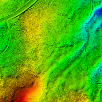
A LiDAR LAS file can have its point clouds classified under a few standard classes e.g. Ground, Low Vegetation, Building, etc. For generating a bare earth digital terrain model (DTM) without vegetation and structures, only the points classified as Ground class are necessary. An example is shown below.

It is relatively straightforward to use SAGA GIS to import the LiDAR LAS file, to extract out a subset containing only the ground points, and then to interpolate the points into a bare earth surface model. I tried out the following steps to create an ESRI ArcGrid ASCII file of the bare earth ground surface.

Import the LiDAR LAS file

  1. Start up SAGA GIS. Select Modules | File | Shapes | Import | Import LAS Files.

    The Import LAS Files dialog box appears.
  2. Select the Input File row. Click the [...] button on the right. In the Open dialog box, browse and select the LAS file, e.g. lub_tile1.las. Click Open.

    The selected file name is displayed in the Import LAS Files dialog box.
  3. In the Attributes to import besides x,y,z list, toggle on classification and any other attributes you want.


  4. Click Okay.

    The LAS file is imported into SAGA GIS.
Extract out Ground points
  1. Select Modules | Shapes | Point Clouds | Tools | Point Cloud Reclassifier / Subset Extractor.

    The Point Cloud Reclassifier / Subset Extractor dialog box appears.

  2. Click the Point Cloud row. Choose the newly imported point cloud in the drop down list, e.g. 01.lub_tile1.
  3. Click the Point Cloud Attribute row. Choose classification.
  4. In the Mode of operation row, choose Extract Subset.
  5. In the Method single old value row, type in 2 for Ground class.
  6. In the Method single new value row, type in 2 to keep it the same value in the subset.


  7. Click Okay.

    The point cloud subset of only Ground points is created. By default, the new layer will have the string subset_classification appended to the input name.
Interpolating the bare earth ground surface
  1. Select Modules | Grid | Gridding | Interpolation from Points | Triangulation.

    The Triangulation dialog box appears.
    Note: Other interpolation algorithm is also fine depending on your requirements
    .
  2. In the Points row, choose the newly created subset e.g. 02.lub_tile1_subset_classification.
  3. In the Attribute row, choose Z.


  4. Click Okay.

    The User Defined Grid dialog box appears.
  5. Optional. In the Cellsize row, type in the desired output cell size e.g. 1.


  6. Click Okay.

    The grid layer is created.
Exporting the bare earth surface in ESRI ArcGrid ASCII format
  1. Select Modules | File | Grid | Export | Export ESRI Arc/Info Grid.

    The Export ESRI Arc/Info Grid dialog box appears.

  2. In the Grid system row, choose the grid system of the bare earth surface grid layer, e.g. 1;684x 685y; 312479.7x 5195216.9y.
  3. In the Grid row, choose the bare earth grid layer, e.g. 01.lub_tile1_subset_classification(Triangulation).
  4. In the File row, click the [...] button. Browse and specify the output file name, e.g. C:\Temp\dtm.asc. Click Save.


  5. Click Okay.

    The bare earth ground surface is exported out.

Thursday, July 22, 2010

Create Slope or Slope directions ESRI ArcGrid ASCII files with Global Mapper

Global Mapper can be used to generate terrain slope values or slope directions (aspect) grid files in ESRI ArcGrid ASCII formats from surface elevation data. This is a two part conversion process workflow instead of a straight export from surface elevation data. The conversion to slope values or directions involves: (1) conversion from elevation to slope values/directions in float/grid file format, and (2) conversion from float/grid format to ESRI ArcGrid ASCII format.

Conversion from elevation to slope values/directions in float/grid format
  1. Start up Global Mapper and load up a surface elevation dataset.
  2. Select File | Export Raster and Elevation Data | Export Float/Grid File.

    The Float/Grid Export Options dialog box appears.


  3. Optional: type in the desired sample spacing values and units.
  4. Toggle on Export Slope Values instead of Elevations to export slope values.
    Or toggle on Export Slope Direction Values Instead of Elevations to export slope directions.


  5. Click OK.

    The Save As dialog box appears.


  6. Type in the output file name e.g. slope.flt. Click Save.

    The elevation data is exported out as slope values or slope directions into the output file.
  7. Close Global Mapper.
Conversion from float/grid format to ESRI ASCII ArcGrid
  1. Start up a Global Mapper and load the slope values/directions float/grid file generated in the previous section.


  2.  Select File | Export Raster and Elevation Data | Export Arc ASCII Grid.

    The Arc ASCII Grid Export Options dialog box appears.


  3. Optional: type in the sample spacing values and choose a vertical unit.  Click OK.

    The Save As dialog box appears.
  4. Type in the output file name, e.g. slope.asc. Click Save.

    The slope values/directions ESRI ASCII ArcGrid file is created

Friday, April 30, 2010

Google Gadget for creating charts on Singapore's OneMap

The Singapore Land Authority (SLA) launched an alternative to Google Maps recently - called OneMap. It's built on ESRI's ArcGIS server and it comes with its OneMap Javascript API, which is essentially a wrapper around ESRI's API. This gives me a chance to work with ESRI's Javascript API and I decided to port the Charting Google Mapplet I wrote earlier to OneMap. The figure below is a screen shot of the gadget running in iGoogle's expanded Canvas mode.
This gadget will create pie charts on Singapore's OneMap from text files formatted as comma separated values (CSV). The CSV data must have a header row, SVY21 easting and northing columns to point to the locations to place the charts on. The charts created can be clicked on to show the values. 

For IE8 users, please run in IE7 or IE8 compatibility mode as IE8 breaks OneMap.The figure below shows the problem of OneMap with Internet Explorer 8 on iGoogle. I am not able to determine the source of the problem but you can click IE's Page button and choose Compatibility View Settings to turn add google.com to the Compatibility View websties .


 To run this gadget, click this link http://www.google.com/ig/adde?moduleurl=http://dominoc925-pages.appspot.com/gadgets/chart_onemap_ig.xml&source=imag.


Monday, April 26, 2010

Now GeoMedia can read ArcView Projection Files (*.prj)

The recent GeoMedia hot fix 6.1.7.16 added a new function in the Define Coordinate System File utility to load ArcView coordinate projection files (*.prj). Previously, you could only read in coordinate systems from Microstation type 56 elements in design files (*.dgn) and other GeoMedia coordinate system files (*.csf). Reading in the prj file is similar to reading in the dgn and csf files as shown below.
  1. Click Start | All Program | GeoMedia Professional | Utilities | Define Coordinate System File.

    The Define Coordinate System File dialog appears.


  2. Click Load.

    The Load Coordinate System From File dialog appears.


  3. Click the Files of Type combo box. Choose Projection Files (*.prj). Choose a *.prj file on your system. Click Open.

    The coordinate system is read.

Wednesday, March 10, 2010

Create a digital elevation model (DEM) from a LAS file with FME

I am quite impressed with the capabilities of the surface generation and raster manipulation transformers in FME. Coupled with the rich set of vector feature transformers, you could almost put together a terrain modelling and image processing package. I tried out generating a terrain model in ESRI ArcGrid ASCII format from a LiDAR LAS file and I am quite happy with the results. To do a simple transformation, just do the following:
  1. Start up FME Workbench and create an blank workspace. Choose Source Data | Add Source Dataset.

    The Add Source Dataset dialog box appears.

  2. Choose ASPRS Lidar Data Exchange Format (LAS) in the Format drop down list. In the Dataset field, click the Browse button and select a LAS file e.g. 288_4320.LAS. Click OK.

    The Select Feature Types dialog box appears.

  3. Toggle off header and variable_length_header (optional). Click OK.

    The source dataset is added to the workbench.
  4. Select Destination Data | Add Dataset.

    The Add Destination Dataset dialog box appears.

  5. In the Format drop down list, choose ESRI ASCII Grid. In the Dataset field, click Browse and choose an output folder e.g. C:\data. Click OK to close the Add Destination Dataset dialog box.

    A message appears to confirm the addition of a new feature type.
  6. Click Yes and OK to add a new Feature Type to the workbench.

    The destination dataset is added to the workbench.
  7. Drag and drop the RasterDEMGenerator transformer and connect the source and destination datasets with the transformer as shown below.


  8. Open up the RasterDEMGenerator Parameters. In the Output DEM X Cell Spacing and Output DEM Y Cell Spacing fields, type in a cell spacing value e.g. 1 as shown below. Click OK.


  9. Run the translation.

    The ESRI ASCII ArcGrid DEM file is generated and can be displayed in a terrain model viewer.