Showing posts with label GeoMedia Terrain. Show all posts

Friday, August 28, 2009

QC digital terrain model for isolated spikes with color gradients

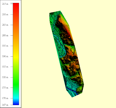
A quick way to find out whether your digital terrain model file has isolated high points or spikes is to display the terrain model with a color gradient from blue to red as shown in the Global Mapper screenshot below.

In this example, the terrain surface is mostly shaded in blue tones. That is a good indication that there are some elevation spikes somewhere in your terrain model.

A screenshot of a digital terrain model file with no high points is shown below. A good terrain surface is shaded evenly with the colors nicely balanced from blue to red as you go from lower elevations to higher elevations.

This is one way to quickly check your digital elevation models for the presence of isolated elevation spikes.

Wednesday, June 25, 2008

GeoMedia Terrain's Unintuitive Terrain Models Dialog Box

The first time I launched the Terrain Models command, I was dumbfounded for a while. Quite a while. I was supposed to build a terrain model using this dialog but there are no obvious indicators to guide me along. The layout and visual arrangement of the buttons, list boxes and labels do not tell me which item I should click on first.

How was I to know that you have to select a Geomorphic data store or a grid data store label and drag the item and drop it on one of the labels: Grid Terrain model or TIN terrain model? Only after reading the online document Working with GeoMedia Terrain that I learn about how to do it. Intergraph need to redesign this dialog box for better user interaction.

Monday, June 2, 2008

Brief Initial Look at GeoMedia Terrain 6.1

I have received the GeoMedia Terrain 6.1 CD from Intergraph and promptly installed it on my computer. The product's graphical user interface looks exactly the same as version 6.0 as indicated in the release notes. I connected successfully to my previous terrain warehouses - so far so good. Then I tried the DataStores command and click on some grid and geomorphic data stores - no high level CPU or disk drive crunching activities as happened previously sometimes on version 6.0 - good.

I tried some more commands - Color Coded and Shaded Relief, and Import Grid DataStore and found that Intergraph introduced new bugs. Previously in version 6.0, the Color Coded and Shaded Relief command will save the shaded relief image files to the image data path defined by the terrain options' preference set. Similarly, the Import Grid DataStore command will open the elevation data path by default as defined by the terrain options' preference set. Now, they open up the C:\ path irregardless of what was set in the terrain options.

At first glance, GeoMedia Terrain 6.1 feels more robust and better suited to a production environment. The path problem is a bit irritating but I can live with it.

Friday, May 23, 2008

Validating Geometries with Z Values

GeoMedia Fusion 6.0 has a useful command - Advanced Validate Geometry to validate and correct 3-D geometries like contour lines, drain lines, lakes etc. before loading into GeoMedia Terrain geomorphic datastores. The command can detect the following anomaly types with regards to the Z values:
  • Area not closed in Z-plane
  • Z out of range
  • Not monotonic
  • Not flat
  • Z breaks
Area not closed in Z-plane Anomaly Check
This anomaly check is great for validating polygons to ensure that the first and last points are vertically closed i.e. have the same Z value.

Z Out of Range Anomaly Check
The Z out of range check will ensure that the geometries fall within a specified minimum and maximum range.

Not Monotonic Anomaly Check
Useful for validating geometries representing drainage lines; this will verify that the geometries have uniformly increasing or decreasing Z coordinates.

Not Flat Anomaly Check
Good for validating flat geometries such as lake polygons, contour lines.

Z Spike Anomaly Check
This check will look for spikes or abrupt changes in the Z coordinates of geometries.

Z Break Anomaly Check
A Z break refers to consecutive points of a geometry on the same XY position but with different Z coordinate.

Using the Advanced Validate Geometry Command

  1. From the GeoMedia Professional pulldown menu, select Fusion > Advanced Geometric Validation > Validate Geometry.

    The Advanced Validate Geometry dialog box appears.


  2. In the Input tab, toggle on the features you want to validate.
  3. Click the Anomalies tab.
  4. Expand the Anomaly Types node and toggle on the Z (height) checks you want to validate for.


  5. Select a Z (Height) anomaly type check e.g. Z Out of Range and define the Anomaly Properties e.g. Minimum Z. For some anomaly types, there would be an option to auto-fix the anomaly.


  6. Click the Output tab.


  7. Type in the name of the queue and/or the name of the query.
  8. Click OK to start the validation process.
  9. You can use the Queued Edit command to review the validation results and correct the geometries using GeoMedia Professional's commands if necessary.

Wednesday, May 21, 2008

Elevation Tagging with GeoMedia

It is actually very simple to do elevation tagging with GeoMedia and you don't have to use GeoMedia Professional. I'm going to show you how to setup GeoMedia to do it.

For instance, you may have contour vector lines that you want to tag with elevations as part of a digital terrain workflow. The contours feature class needs to have an attribute field for storing the elevation; if it doesn't have, you can use the Feature Class Definition command to create one. Next, find out the elevation range and interval of the contours, say from 0 to 4500.

  1. Select Legend > Add Thematic Legend Entry.

    The Add Thematic Legend Entry dialog box appears.

  2. In the Input feature combo box, select the contours feature.
  3. Choose Unique Value Thematic type.
  4. In the Attribute for classification combo box, select the elevation attribute field.
  5. Define the Style, Value, and Label for each contour elevation you have, e.g. 0, 500, 1000, ... 4500.

    Note: Choose colors that you can distinguish easily from the untagged contours, e.g dull earth colors. You could also choose bold black colors for major elevations and gray colors for intermediate elevations so you can see patterns in the map window.

  6. Define the Style for the Other values.

    Note: This style is used for unassigned contours, so choose a contrasting color e.g. red that can be easily distinguished from the tagged contours.

    The Add Thematic Legend Entry dialog box may look like this.


  7. Click OK.

    The Legend and the map window displays the newly created thematic mapping.

    Note: The unassigned contours are displayed in red and are easily distinguished from the tagged contours.

  8. Double click on the unassigned contours.

    The properties dialog box appears.

  9. Type in the elevation value and press OK.

    The newly tagged contours feature no longer displays in the untagged style.

  10. Continue to assign elevation to all untagged contours until finished.
After you have completed the elevation tagging, you can use the Functional Attributes command or the Update Attributes command to update the contours feature class' geometries with the newly assigned elevation attribute.

Wednesday, May 14, 2008

Using Update Attributes to Set Contour Elevation

An alternative method to set the elevation value of a contour line is to use GeoMedia's Update Attributes.

  1. Use the Selection Tool to select one or more contour lines with the same elevation.
  2. From the GeoMedia's pulldown menus, select Edit > Attribute > Update Attributes.

    The Update Attributes dialog appears.


  3. In the Update Attributes dialog, expand the Select Set nodes and select the feature name.
  4. On the right side of the Update Attributes dialog, click in the Value field of the feature's geometry field, e.g. LinearGeometry.
  5. Click Expression.

    The Expression dialog box appears.


  6. In the Categories list box, click Geometry.
  7. In the Functions list box, double click the function SETZ.
  8. In the Attributes list box, double click the attribute Input.{GeometryFieldName} e.g. Input.LinearGeometry.

    The Expression field should read like this:
    SETZ(Input.LinearGeometry)

  9. Type in a comma before the closing parentheses.
  10. Type in the elevation to set in the Expression field, e.g. 1000. The elevation should be in the units of the GeoWorkspace Coordinate System's Vertical Storage Unit.

    The Expression field should now read something like this:
    SETZ(Input.LinearGeometry,1000)

    Note: If the elevation you want to type in is not in the Coordinate System's Vertical Storage units, then you will have to do a conversion yourself.

  11. Click OK.

    The selected contour line's elevation is adjusted to the new elevation.


Tuesday, May 13, 2008

Setting the Elevation of Contours using Edit Geometry

One of the common tasks in the terrain modeling workflow is to interactively tag vector contour lines with an elevation. I could not find a command in GeoMedia Terrain 6.0 or any steps in the delivered documentation. I could do the job with GeoMedia's Functional Attributes but I have to calculate the elevation values manually taking into account the storage units and my height unit preference - that would definitely scare users away. I later found out that I could also use GeoMedia Professional's Edit Geometry command. Here are the steps to tag contour lines with elevation with the Edit Geometry command.
  1. Activate the Selection Tool.
  2. Select a contour line geometry in the map window.


  3. In the GeoMedia Professional Edit pulldown menu, select Edit > Geometry > Edit.

    All the vertices in the contour line are displayed as black handles.


  4. Click on a vertex handle on the contour line to select it.

    The selected vertex is displayed as a purple filled circle.


  5. Right click in the map window to bring up the Edit Geometry context menu.


  6. Choose Select All.

    All the vertices are selected and are displayed with purple filled circles.

  7. Right click again in the map window to bring up the Edit Geometry context menu again.
  8. This time, choose Edit Height.

    The Edit Height dialog appears.

  9. In the Edit Height dialog, type in the height value.
  10. Click OK.

    The height of the contour line is changed to the new value.

  11. Press ESC.

    The Edit Geometry command is deactivated.
The good points about Edit Geometry are that the height units follow the user's preferences set and the height changes can be undone. On the downside, the workflow is still a little cumbersome having to select all the vertices (which take a while if a contour line has a lot of vertices). I just might decide to write a GeoMedia custom command just to set the elevation of geometries.

Friday, May 9, 2008

GeoMedia Terrain 6.1 Released

Intergraph has just released a new version of GeoMedia Terrain version 6.1 in April. According to the release notes, this release is for delivering a version of GeoMedia Terrain that is compatible with GeoMedia 06.01.00. Enhancements in the new version include:
  • Performance improvements
  • The ability to take in larger data volumes than version 6.0
  • New Primary InterOp Assemblies for .NET application development
  • Windows Vista support and 64-bit hardware compatible
I have encountered poor performance and inexplicable crashes while writing a training course guide for GeoMedia Terrain. I have just ordered a copy of the software and once I receive the DVD, I hope to give the new version the run through and see whether Intergraph has fixed the problems.

Monday, April 14, 2008

Editing GeoMedia Terrain Models

The documentation that comes with GeoMedia Terrain 6.0 does not provide clear details on practical usage of the terrain model editing commands. While writing a GeoMedia Terrain training course guide, I figure out that displaying the terrain model vertices and triangle edges goes a long way in helping users understand how to use the editing commands. By the way, this is not described in the delivered documentation.

Displaying Terrain Model Triangle Edges and Vertices
  1. In the GeoMedia menus, select Legend > Add Legend Entries.

    The Add Legend Entries dialog box appears.

  2. Expand the Terrain Warehouse connection node that contains your TIN terrain model.
  3. Check the {YourModelName}_TriangleVertices feature on.
  4. Check the {YourModelName}_TriangleEdges feature on.

    The Add Legend Entries dialog box should like as shown below.
  5. Click OK.

    The triangles and edges are displayed in the active map window.

Editing Terrain Model Vertices
Now that you can see the triangle vertices and edges, editing the model is so much easier.
  1. In the GeoMedia menus, select Terrain > Edit > Edit Model Vertices.

    The Edit Vertices dockable control is displayed.
Insert Vertices
  1. In the Action drop down list, choose Insert.

    You are prompted to "Select vertex to insert" in the GeoMedia status bar.

  2. In the Operate on drop down list, choose Individual vertices.
  3. In the Z field, enter an elevation value e.g. 5000.
  4. In the map window, click a new vertex point.

    A new vertex is created in the map window. You can see the model triangle edges and points dynamically adjust themselves to accomodate the new vertex.

  5. You can click to insert more vertices.
  6. If you made a mistake, you can do a mouse right click in the map window.

    The Edit Model Vertices context menu pops up.

  7. Choose Undo to remove the last vertex.
  8. After you have inserted all the vertices that you want, do a mouse right click in the map window.
  9. Choose Update Model to save the new vertices permanently into the terrain model.
  10. Right click and choose Cancel to terminate the command.
Move Individual Vertices
  1. In the Action drop down list, select Move.

    The cursor becomes a cross hair cursor. You are prompted to "Select vertex to move".

  2. In the map window, click on a vertex.

    The vertex is highlighted and you are prompted to "Select location to move".

  3. Click on the new location in the map window.

    The selected vertex is moved to the new location.

  4. In the map window, do a mouse right click and select Update Model.

    The changes are saved permanently.
Delete Individual Vertices
  1. In the Action drop down list, select Delete.

    The cursor becomes a cross hair. You are prompted to "Select vertex to delete".

  2. In the map window, click on a vertex.

    The selected vertex is removed and you are prompted to "Select another vertex to delete".

  3. In the map window, right click and choose Update Model.

    The changes are saved permanently.
Move Vertices in a Selection Set
  1. Click on the Select Tool icon.
  2. Then click on two or more vertices in the map window. Note that if you want to add to the selection set, then you need to press down the CTRL key on the keyboard while clicking.
  3. After you are done with selection, in the Action drop down list, select Move.
  4. In the Operate on drop down list, choose Select set.

    You are prompted to "Input X,Y values to move the vertices.

  5. Then key in the relative X and Y offsets in the X and Y fields, e.g. X=500, Y=500.

    You are prompted to Click Process Move to move the vertices.

  6. Do a mouse right click in the map window. In the context menu, choose Process Move.

    A message box appears showing the number of vertices moved and the number failed.

  7. Click OK.

    The vertices in the selection set are moved by the relative X and Y offsets.

  8. In the map window, right click and choose Update Model to save the changes permanently.
Editing Terrain Model Z Elevation Values
You need to activate the Edit Z dockable control toolbar to perform editing on the Z-elevations of the terrain model. Select Terrain > Edit > Edit Z in the GeoMedia menus.

The Edit Z dockable control appears.


Edit Individual Vertex's Z Value
  1. In the Edit Z control's Applies to drop down list, select Individual vertices.

    You are prompted to "Select vertices to edit".

  2. In the control's Operator field, choose None.
  3. In the control's New Z field, enter an elevation e.g. 6000.
  4. Click on an existing vertex in the map window.

    You are prompted to "Select another vertex or choose 'Edit Vertices' to perform the edit.

  5. Click on additional vertices.
  6. When you are done, right click in the map window and choose Edit Vertices to perform the edits.

    The message box appears showing the number of vertices edited or failed.

  7. Click OK.

    All the selected vertices' elevation values are updated.

Edit Z of Vertices with the Same Z
  1. In the control's Applies to drop down list, select Vertices with same Z.
  2. In the control's Original Z field, enter the Z elevation of the vertices to change e.g. 6000.
  3. In the control's Operator drop down list, select an operator e.g. +.
  4. In the control's Operand field, enter the delta value e.g. 500.

    The control's New Z field shows the resultant Z value,
    e.g. New Z= {Original Z=(6000)}{Operator=(+)}{Operand=(500)}=6500.

  5. In the map window, right click and choose Edit Vertices.

    After processing, the message box showing the number of vertices edited or failed appears.

  6. Click OK.
  7. In the map window, right click and choose Update Model to save the changes permanently.