- Start the FME Workbench.
- Select Readers | Add Reader.
The Add Reader dialog box appears.
- In the Format field, choose ASPRS Lidar Data Exchange Format (LAS).
- In the Dataset field, click the browse [...] button. Select two or more LAS files. Click OK.
The Reader is added to the Main pane. - From the Transformer Gallery pane, drag and drop the PointCloudCombiner transformer onto the Main pane.
- Select Writers | Add Writer.
The Add Writer dialog box appears.
- In the Format field, choose ASPRS Lidar Data Exchange Format (LAS).
- In the Dataset field, click the browse [...] button and define the output folder.
- Click OK.
The following prompts will appear. Click Yes and OK.

- Connect the Reader, transformer and Writer as shown.

- Run the translation.
The LAS files are merged into a single file.

About Geospatial Applications, FME, Visual Studio, gvSIG, Global Mapper, Programming, LiDAR, GIS, Google Maps, SAGA GIS, Android, QGIS
Showing posts with label safe fme. Show all posts
Showing posts with label safe fme. Show all posts
Monday, October 15, 2012
Merge LiDAR LAS files using FME
If you want to merge multiple LiDAR LAS files into a single, combined file, then it is possible to use the Safe FME Workbench to quickly put together a simple workflow to do the job. All that is required is to define a Reader for the multiple LAS files, connect that to the PointCloudCombiner transformer and output to a LAS file Writer. The following illustrates the steps.


Monday, August 22, 2011
Export ground points from a LAS file to ASCII CSV file using FME
This is one of the typical LiDAR file conversion task - converting a LAS (*.las) file to an ASCII XYZ or CSV (*.csv) file. It can be done with any number of free and commercial software. It is a simple matter to define a workspace using the FME Workbench from SAFE to do the job. Here are the steps that I used to export out only ground points from a LAS file into an output ASCII CSV file.
- Start the FME Workbench. Create a blank workspace.
- Select Readers | Add Reader. In the Format field, choose ASPRS Lidar Data Exchance Format (LAS). Choose a dataset e.g. C:\data\lub_tile1.las. Click OK.

- Select Writers | Add Writer. In the Format field, choose Comma Separated Value (CSV). Choose an output dataset e.g. C:\Temp\.

- Click Parameters. If necessary, change the extension from the default csv. Choose another Separator Character if comma is not wanted. Click OK.

- Click OK again.
The prompt appears.
- Click Yes.
The Feature Type Properties dialog box appears.
- In the Feature Type Name field, type in the output CSV file name e.g. outascii.
- Click the User Attributes tab. Define number attributes for the X,Y,Z values as shown below. Click OK.

- From the Transformer Gallery, drag and drop the PointCloudCoercer, CoordinateExtractor, and Tester transformers onto the workspace.
- Connect up the source, transformers and destination as shown below.

- Open the PointCloudCoercer Parameters. Change the Output Geometry to Point. Click the Point Components to Preserve button and select all. Click OK.

- Open the Tester Parameters. Define a Test Clause as shown below to allow only ground points (class=2). Click OK.

- Run the translation.
The output ASCII CSV file is created.


Monday, March 28, 2011
Thinning a LAS file with FME 2011
FME Desktop 2011 comes with a bunch of revamped transformers designed to work with point clouds - specifically LiDAR datasets. In previous versions, FME can only read in LiDAR LAS files but I'm thrilled with this new version now since it comes with a LAS file writer.
I tried out the new point cloud transformers by performing one of the standard LiDAR processing production tasks - thinning the data by resampling at every nth point. It is simple to build a transformation workspace to do the job. Here are the steps:
I tried out the new point cloud transformers by performing one of the standard LiDAR processing production tasks - thinning the data by resampling at every nth point. It is simple to build a transformation workspace to do the job. Here are the steps:
- Start up FME Workbench 2011.

- Click Blank Workspace.

- From the Windows Explorer, drag a LAS file and drop it onto the FME Workbench Main pane.
The Add Reader dialog box appears.
- Click OK.
- Activate the Transformer Gallery tab on the left.
- Find and select the PointCloudThinner transformer in the Transformer Gallery tree list. Drag and drop it onto the Main pane.
- Select Writers | Add Writer.
The Add Writer dialog box appears. - Choose the ASPRS Lidar Data Exchange Format (LAS). Browse and select the output dataset.
- Click OK. Click Yes and OK to the next few prompts.
- Connect the datasets and transformer as shown.
- Open up the PointCloudThinner Parameters.
The PointCloudThinner Parameters dialog box appears. - Choose the Keep Every Nth Point Thinning Type. In the Amount field, type in a value e.g. 10.

- Click OK.

- Run the translation.
The LAS file is thinned


Monday, March 15, 2010
Create LiDAR intensity GeoTiff images with FME
The raster transformers in FME can be used to create LiDAR intensity images in GeoTiff format. In my previous post, I created intensity images with the ImageRasterizer transformer but the resultant images are not that great. A better way is to form an intensity surface from the LiDAR points using the RasterDEMGenerator and generate the output GeoTiff intensity image. The detailed steps I did are described below.


- Start up the FME Workbench and open a blank workspace.
- Select Source Data | Add Dataset. Choose ASPRS Lidar Data Exchange Format (LAS) as the source format. Click Browse and choose a LAS file.
The Add Source Dataset dialog box appears.
- Click OK.
The Select Feature Types dialog box appears.
- Toggle off header and variable_length_header (optional). Click OK.
The source dataset is placed on the workbench. - Select Destination Data | Add Destination Dataset.
The Add Destination Dataset dialog box appears.
- In the Format field, choose GeoTIFF. Click Browse and choose an output folder as the dataset. Click OK.
The prompt appears.
- Click Yes.
The Feature Type Properties appears.
- If you like, click the Parameters tab and define the output GeoTiff parameters e.g. compress method, world file generation etc. Click OK.
The destination dataset is added to the workbench. - Drag and drop the CoordinateFetcher, GeometryRemover, 3DPointAdder, RasterDEMGenerator, RasterInterpretationCoercer transformers onto the workbench. Connect them with the source and destination datasets as shown below.

- Open the CoordinateFetcher transformer's parameters and set as shown below.

- Open the 3DPointAdder transformer's parameters.Choose _x, _y, and Intensity as the X Value, Y Value and Z Value.

- Open up the RasterDEMGenerator's parameters. Type in the Output DEM X Cell Spacing and Y Cell Spacing e.g. 1.

- Open up the RasterInterpretationCoercer transformer's Parameters. Choose the Destination Interpretation Type e.g. Gray8. In the Convert from Numeric to Color field, choose Cast.

- Run the translation.
The intensity GeoTiff file is created.


If you find the intensity image looks blown out (too many white spots), you can add in the ExpressionEvaluator transformer to adjust the intensity values before passing them into the RasterDEMGenerator transformer as shown below.

In the ExpressionEvaluator's Properties, scale down the intensity values by multiplying with a factor e.g. 0.25 as shown below to ensure the values fit into the 8-bits grayscale range (0~255). I prefer using the ExpressionEvaluator than the RasterInterpretationCoercer to do this task as I wasn't too happy with the results from the Coercer's Numeric to Color parameter.

Wednesday, March 10, 2010
Create a digital elevation model (DEM) from a LAS file with FME
I am quite impressed with the capabilities of the surface generation and raster manipulation transformers in FME. Coupled with the rich set of vector feature transformers, you could almost put together a terrain modelling and image processing package. I tried out generating a terrain model in ESRI ArcGrid ASCII format from a LiDAR LAS file and I am quite happy with the results. To do a simple transformation, just do the following:
- Start up FME Workbench and create an blank workspace. Choose Source Data | Add Source Dataset.
The Add Source Dataset dialog box appears.
- Choose ASPRS Lidar Data Exchange Format (LAS) in the Format drop down list. In the Dataset field, click the Browse button and select a LAS file e.g. 288_4320.LAS. Click OK.
The Select Feature Types dialog box appears.
- Toggle off header and variable_length_header (optional). Click OK.
The source dataset is added to the workbench. - Select Destination Data | Add Dataset.
The Add Destination Dataset dialog box appears.
- In the Format drop down list, choose ESRI ASCII Grid. In the Dataset field, click Browse and choose an output folder e.g. C:\data. Click OK to close the Add Destination Dataset dialog box.
A message appears to confirm the addition of a new feature type. - Click Yes and OK to add a new Feature Type to the workbench.
The destination dataset is added to the workbench. - Drag and drop the RasterDEMGenerator transformer and connect the source and destination datasets with the transformer as shown below.

- Open up the RasterDEMGenerator Parameters. In the Output DEM X Cell Spacing and Output DEM Y Cell Spacing fields, type in a cell spacing value e.g. 1 as shown below. Click OK.

- Run the translation.
The ESRI ASCII ArcGrid DEM file is generated and can be displayed in a terrain model viewer.


Thursday, December 17, 2009
Flagging intersection points with elevation differences
Typical GIS applications have the capability to determine unbroken intersections but only from the perspective of a 2D plane i.e. as if the spatial intersection analysis is done only after the line work is projected entirely onto the 2D plane; if the line work has a elevation or Z component, then the Z component is ignored entirely in the analysis. In 3D GIS applications like terrain modeling, sometimes it is useful to be able to determine the elevation difference of the line work at the point of intersection. If one spatial feature represents a lake, then a river line feature flowing out of the lake should have the same elevation at the point of intersection. It would be useful to be able to flag the intersection points that have elevation differences.
In the example dataset below, there are a few line features with different elevation values - the values are labelled along the line work. All of them are at 0 elevation except for one, which is on 10 elevation.

We want to flag out the intersection point where there is a difference in elevation. One of the tools that can help us perform this is Safe FME. FME has some transformers that you can string together to perform the flagging of intersection points with elevation differences.
- Run FME Workbench. Add in a Source Dataset e.g. lines.shp. Add in a Destination Dataset e.g. flags.shp.
- Drag and drop the Intersector, Matcher, Counter Transformers onto the Main pane. Connect them up as shown in the figure below.

Note: the Counter transformer is used to simply count the number of flags.
- Open up the Intersector transformer's Parameters. The settings should be set as shown below.
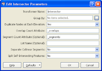
Note: Duplicate Nodes as Each Elevation should be set to Yes. Then when an elevation difference is detected at the point of intersection, the Intersector transformer will output 2 nodess.
- Open up the Matcher transformer's Parameters.The settings should be set as shown below.

Note: The Matcher will find(match) all duplicate nodes i.e. the nodes that have elevation differences.
- Run the translation.
The intersection points where there are elevation differences are flagged (shown as a red cross below).


Friday, November 20, 2009
Flagging dangles (free end points) with FME

The steps are described below.
- Start the FME Workbench and open a blank workspace.
- Select Source Data > Add Dataset to add in a source dataset.
For this example, I added in a ESRI shape file as the source dataset.

- Select Destination Data > Add dataset to add in a destination dataset.
I chose to output the dangle flags as ESRI Shape point file.


- Drag and drop the following transformers onto the workbench:
- CoordinateFetcher (2 times)
- GeometryRemover
- 2DPointAdder
- Matcher
- Connect the transformers with the source and destination datasets as shown below.

- Open up the first CoordinateFetcher's properties.In the Index field, type in 0. Click OK.

Note: this transformer will extract the line work's first vertex into the fields _x, _y, and _z.
- Open up the second CoordinateFetcher's properties. In the Index field, type in -1. Click OK.

Note: this transformer will extract the last vertex of the line feature into the fields _x, _y, _z.
- Open up the 2DPointAdder transformer's properties. In the X-Value field, choose _x. In the Y-Value field, choose _y. Click OK.

Note: the 2DPointAdder will create a new point from the _x and _y fields.
- Open up the Matcher transformer's properties.In the Match Geometry field, choose 2D.
Note: In this example, in the Attribute(s) to match field, I chose _x, _y but this is redundant because the 2D point geometry already has the _x and _y coordinates. This field can be left blank.

- Run the translation.
The dangles are created and flagged as red crosses below.


Subscribe to:
Posts (Atom)
